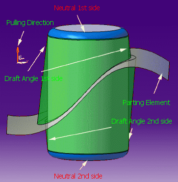
The Draft Both Sides capability allows you to generate drafted faces on each side of a parting element you determine.
This task includes two scenarios.
-
Using Two Different Computation Modes: shows you how to draft two faces with reflect lines by using two different computation modes: First, you will specify two different angle values, one for each opposite side, then you will use an option that adjusts the generated faces on the parting element.
Using Two Different Computation Modes
-
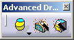
Click Draft Both Sides
 in the Advanced Dress-up Features toolbar
 .
.
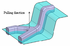
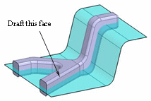
The Draft Both Sides dialog box is displayed. By default, it is expanded to let you see helping images. In the default helping image, the text in red indicates the geometry you need to select. Conversely, the text in green indicates the geometry already selected by default. Helping images vary according to the parameters you set during your design.A default pulling direction (xy plane) is displayed in the geometry.
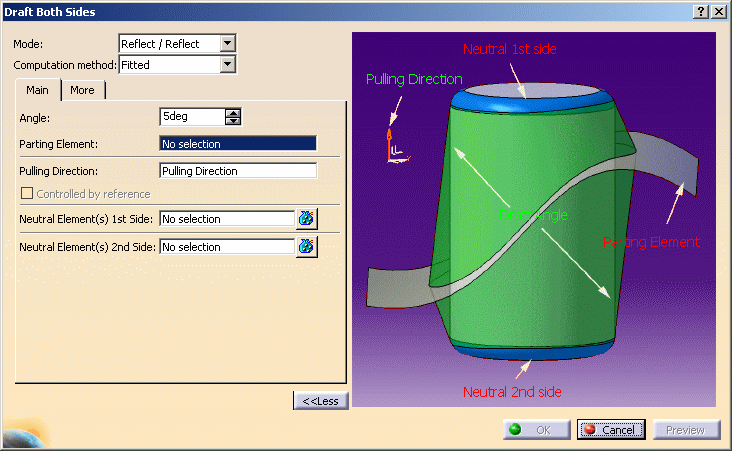
Selecting Less hides the dialog box 2D viewer. Note that the last state of this 2D viewer is memorized when the dialog box is closed by clicking OK. As a result, once you are familiar with the Draft Both Sides capability and you no longer need helping images, just minimize the dialog box before clicking OK.
-
To draft two faces with reflect lines, keep Reflect/Reflect, which is the default option, on. Using this option, the neutral faces are the filleted edges and the faces to draft are automatically defined by the neutral elements as being the tangent faces.
-
To be able to specify two different angle values select Independent in the Computation method combo list.
The helping image reflects the parameters you have selected and the dialog box now displays two angle value fields: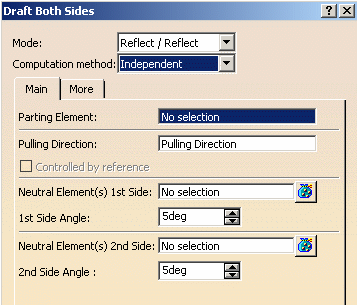
-
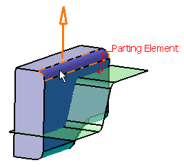
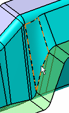
Select Parting Element and select the green surface as the parting element.
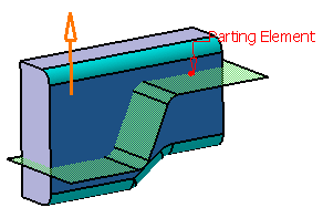
As indicated in the helping image, the "Parting Element" text is now in green, indicating that the required geometry has been selected.
-
Click the Neutral Element 1st Side field and as the neutral element you need, select the fillet as shown:
-
In the 1st Side Angle field, enter 6 as the draft angle value you want to assign to this face.
-
To define the second face you want to draft, click the Neutral Element 2nd Side field and select the second fillet.
-
In the 2nd Side Angle field, enter 10 as the draft angle value you want to assign to this face.
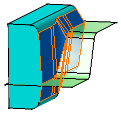
Both faces to be drafted are now selected. The application displays the reflect line in pink. -
Click OK to confirm.
Two faces on each side of the parting element are drafted. Each of them is assigned a distinct angle value.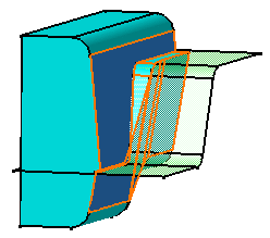
Due to the use of the different angle values you have set, this operation results in a "step" where both drafted faces meet. 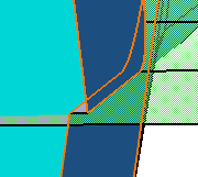
-
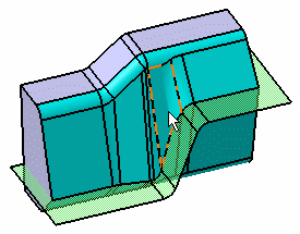
Double-click the draft feature in the specification tree to remove this step.
-
Set the Fitted option. This option adjusts the resulting faces on the parting element you chose.
Using the Parting Line Adjustment Option
You will use Parting Line Adjustment to ensure that later on you will be able to apply machining techniques onto the part. To illustrate that option, let's consider the part we used in the previous scenario.
-
Double-click Draft.1 in the specification tree to edit it.
-
Enter 17 degrees to change the draft angle value you previously set to the draft.
-
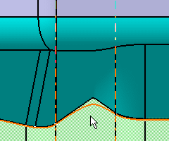
This excessive value does not reflect angle values designers usually use, but this lets us quickly see what happens next. You obtain a draft which is not satisfactory. As indicated by the arrow, the curvature radius would invalid any machining process because it is too small:
-
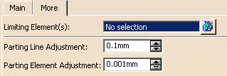
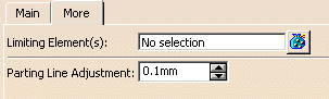
Click the More tab.
-
Keep 0.1mm as the parting line adjustment value.
-
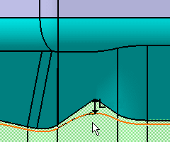
If you click Top View
 in the View toolbar, the curvature radius causing trouble for
being too small, becomes more visible, as pointed to by the arrow:
in the View toolbar, the curvature radius causing trouble for
being too small, becomes more visible, as pointed to by the arrow: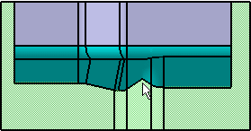
-
Now, changing the parting line adjustment value to 0.7 mm would add material up to the curve pointed to by the arrow. Consequently, the curvature radius would be more acceptable.
-
Changing the parting line adjustment value to 0.9mm would let you obtain an even larger curvature radius:
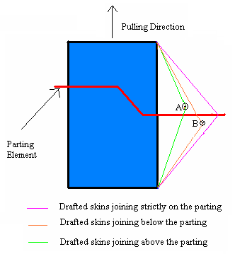
Concretely speaking, when setting the parting line adjustment parameter, you define a length value that sets a maximum thickness to be added to the draft to enlarge the wrong curvature radius. As illustrated in the case just above, that length is represented by L. The chosen value is 0.9mm, which means that L might be 0.9mm or even a little bit less.
Considering the rest of the curvatures of the draft feature, depending on the part shape, that thickness will most often be thinner, but will never exceed the value you entered.Methodology
The Parting Line Adjustment option thus adds material to the part. If then you decide to use it, you should keep in mind that you need to enter reasonable values not to add too much material prior to machining processes. Usually, 0.1mm set as the default value provided by the application, proves to be efficient most of the time.
Concerning draft angle values, again make sure the value you enter does not add too much material. In the worst cases, this would prevent you from removing parts from molds.
In other words, a successful draft operation requires a fine tuning between the draft angle value you set and the parting line adjustment you may perform. The challenge being to add the minimum material to the part.
Useful Tools
Remember that you can always check curvatures by performing Surface Curvature Analyses and draft validity by using the Draft Analysis capability.
Mode
The application offers two modes:
-
Reflect/Reflect: the neutral faces are the filleted edges and the faces to draft are automatically defined by the neutral elements as being the tangent faces.
-
Neutral/Neutral: the neutral selected faces can be propagated by tangency, and the faces to draft can be defined either by the user or automatically by the neutral elements.
When this mode is chosen, radius values are displayed in the geometry
Computation Method
Three computation methods are available:
-
Independent: you need to specify two angle values, as shown in the scenario above.
-
Driving/Driven: the angle value you specify for one face affects the angle value of the second face.
By default, 1st Side Driving is the selected side, meaning that the angle value you specified for the face selected first is the driving value. You can change and select 2nd Side Driving instead.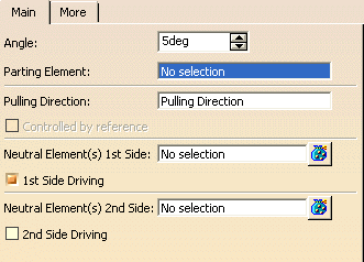
Sometimes, some resulting faces of the "Driven draft" are not apt for being removed from molds. In this case, we recommend you to check this using the Draft Analysis capability.
-
Fitted: performs a draft operation on two opposite sides of the part while adjusting the resulting faces on the parting element you chose. This method is available if you are using the Reflect/Reflect as well as Neutral/Neutral mode.
-
The draft operation can be initialized only if the faces to draft and neutral elements of two sides lay one above another with respect to the pulling direction. This is a limitation to avoid bad performance in initialization phase.
-
There should be at least one common edge between the whole set of faces to draft and each neutral face selected. This is applicable only in Neutral/Neutral mode with Fitted computation method.
-
The draft ribbon propagation fails if the tangent propagation on neutral faces leads to a face to draft or vice versa. So in general for draft operation to succeed the common edges between neutral faces and faces to draft should be sharp. This is applicable only in Neutral/Neutral mode with Fitted computation method.
-
The features in the body to be drafted may get lost because of sewing of draft skin to the body. Sometimes it may cause failure of draft operation.
Pulling Direction
Contextual commands creating the reference elements you need are available from the Selection field:
-
Create Line: For more information, see Creating Lines.
-
Create Plane: see Creating Planes.
-
X Axis: the X axis of the current coordinate system origin (0,0,0) becomes the direction.
-
Y Axis: the Y axis of the current coordinate system origin (0,0,0) becomes the direction.
-
Z Axis: the Z axis of the current coordinate system origin (0,0,0) becomes the direction.
If you create any of these elements, the application then displays the corresponding icon next to the Selection field. Clicking this icon enables you to edit the element.
Editing Drafts Created Via Advanced Draft
Double-clicking on both side draft features created using
Advanced Draft
![]() displays the Draft Both Sides dialog box in which changing
parameters will be done more easily.
displays the Draft Both Sides dialog box in which changing
parameters will be done more easily.