Machining and Slope areas can be used to define different zones on a
part.
First you define the Machining/Slope areas and then you assign an operation
to each of them.
This is a useful approach if, before you start machining, you are aware that
the part has areas
that will require different types of operation.
Another feature of machining areas is their ability to be divided into
horizontal, vertical and sloping areas
and have operations assigned to these areas.
Click Machining/Slope area
![]() , then the
geometry of the part to
machine in the Geometry tab.
, then the
geometry of the part to
machine in the Geometry tab.
The Slope Area option gives access to:
- the Define tab,
- the Edit tab,
- the Operations tab to assign machining operations to the defined areas.
Main Panel
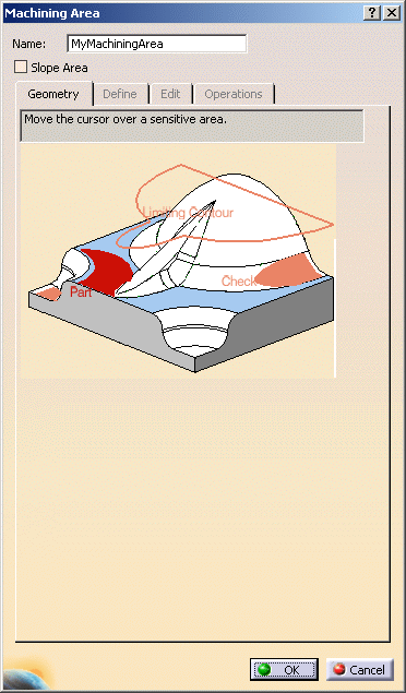
Name
You can assign a name to the Machining/Slope areas feature, or keep the name proposed by default.
Slope Area
Select the Slope Area check box to create slope areas and to access the corresponding parameters.
Geometry
With the sensitive icon, you can select the following elements:
- Part.
- Check element. The check is often a clamp that holds the part and therefore is not an area to be machined.
- Area to avoid (small
light brown corner near the part selection area).
This is in fact a list of faces removed from from the list of faces built from the Part.
Those removed faces are not taken into account to compute the tool path.
Use Area to avoid for a quick definition of a sub-element of the Part you want to machine.
For example, you want to machine the Part below, but not its pocket.
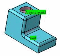
To do so: - select the whole part as the Part,
- then define the Area to avoid by selecting the faces of the pocket.
- Limiting contour which is the contour that defines the outer machining limit on the part.
A longer alternative would be to define the Part face by face.
A machining area can be:
- the whole part (for example, in roughing),
- a subset of the faces on the part,
- a subset of faces on the part with a limiting contour.
- do not select parts in the PPR tree that are the output of assembly operations (Add,Remove,Assembly),
- but select all the faces of this sub-element in the 3D Viewer.
Define
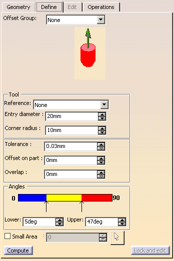
Offset Group
You can select an offset group from the list, when available.
 |
Click this icon to define the tool axis.
Tool
Reference, Entry diameter, Corner radius
You can either:
- select an existing tool from the Reference list, or
- define one with its entry diameter and its corner radius.
Tolerance
Machining tolerance that you want to use for the slope area.
Offset on part
Offset that is computed for the slope area with respect to the part.
Overlap
When slope areas of different types are defined, there may be a gap
between them,
resulting in material left on the part.
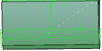
To avoid this, you can define an overlap, i.e. a distance on which two
slope areas will cover each other,
making sure that the whole part is machined.
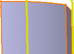
- Overlap=0, the slope areas end on the same line
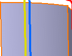
- Overlap=5, the slope areas cover each other.
Angles
Define three types of area on the part:
- blue defines horizontal areas
- yellow defines sloping, transitional areas between vertical and horizontal,
- red defines vertical areas.
Defines the lower limit of the sloping area.
Defines the upper limit of the sloping area.
 |
For example, here surfaces that are considered to be horizontal go from 0°
to 5°,
sloping surfaces from 5°
to 45°
and vertical surfaces from 45°
to 90°.
These angles are computed with respect to the tool axis.
Small Area
Merges small areas in larger surrounding ones.
Click the arrow to select a reference contour.
This will computes
automatically a value below which an area is considered as small and merged
into a larger one.
You can also type a value without selecting a reference contour.
Compute
Computes the slope areas.
Full display of area
Once the slope areas have been computed, this check box displays them
as full areas instead of lines,
making overlapping areas easier to detect.
Lock and edit
Locks the slope areas and gives access to the Edit tab.
Edit
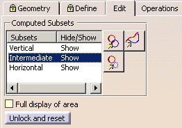
![]() : Deactivates contours in any subsets.
: Deactivates contours in any subsets.
![]() : Reactivates contours of the selected subset.
: Reactivates contours of the selected subset.
![]() : Removes details (unwanted portion of contours) in any subset.
: Removes details (unwanted portion of contours) in any subset.
Full display of area
Once the slope areas have been computed, this check box displays them
as full areas instead of lines,
making overlapping areas easier to detect.
Unlock and reset
Cancels all computations and modifications on slope areas.
Operations
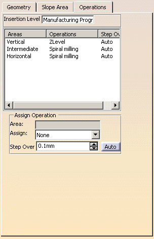
Insertion Level
This data is compulsory. It can be:
- an operation,
- a tool change,
- a Manufacturing Program.
The Assign Operation area is displayed once the Insertion Level is defined.
- If the insertion level associated to the slope area is an operation or
a tool change,
the associated tool is taken into account and affected to the operations of the Slope area. - If the insertion level associated to the slope area is a Manufacturing
Program,
the operations of the slope area are created with no tool.
You can create a Slope area with a reference tool.
- If the insertion level associated to the slope area is an operation
with a tool different from the reference tool,
or if the insertion level is a Manufacturing Program, an additional ToolChange is created.
|
Operation 11 is taken as the insertion level, and one operation is
associated to the slope area.
The specification tree becomes:
|
Used to assign an operation to the machining/slope areas.
- To do so, select one area to which you want to assign an operation and
define the operation parameter in the Assign Operation box that is now available. -
Use the Assign list to select one type of operation, set the Step Over value in the field below.
-
To revert to an automatic step over, click Auto. The value is replaced with the label Auto.