 |
-
Select Explode  . .
-
Select the shuttle you need to explode in the
specification tree or in the geometry area.
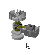 |
 |
You can also use the drag and drop capability (drag the
Explode  icon and drop it onto Shuttle.1 in the specification tree).
 |
| The Explode dialog box is displayed. |
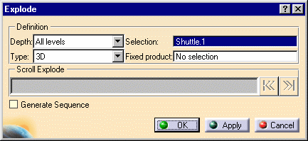 |
-
Set the Depth parameter to First level
(if not already set).
| The Depth parameter lets you choose between a totally
(All levels) or partially (First level)
exploded view. |
-
Set Type to 2D.
| The exploded view is set to the screen plane. |
| You can generate a sequence from the exploded view if
you select the Generate Sequence checkbox before launching
the explode operation. |
 |
For more detailed information refer to
Generating a Sequence from an Exploded
View. |
-
Select the Apply button to perform the
operation.
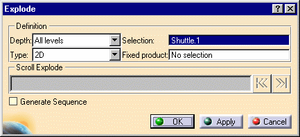 |
| The Scroll Explode field gradually
displays the progression of the operation. The application assigns
directions and distance. Once complete, the resulting exploded view
looks like this: |
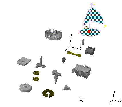 |
 |
This operation enables users to view all components separately
within the same plane. |
-
Select the Apply button to perform the
operation.
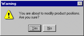
If you select the OK button, the following warning
message is displayed because the exploded view is kept when exiting
the command. In this case, if you need to restore the initial view,
select the Reset
 . . |
 |
-
To print the exploded view, select the
File > Print command.
| The Print dialog box appears. |
-
Once you select the desired settings, select the
Preview button and then the OK button.
|
![]()
![]()