Before you begin, note that:
|
-
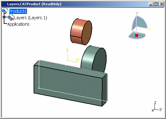
Click the "+" symbol next to Layers, then the "+" symbol next to PadandCylinder, Pad, etc. until you see the following:
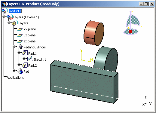
You can now see clearly that the two features are named PadandCylinder and Pad. -
Select View > Toolbars > Graphic Properties to display the Graphic Properties toolbar:

None in the Layer list:  indicates that
there is no current layer, which guarantees that all the contents
of your document are visible. You can assign objects to None:
any object assigned to None is always visible.
indicates that
there is no current layer, which guarantees that all the contents
of your document are visible. You can assign objects to None:
any object assigned to None is always visible.For the moment, you have not yet assigned any objects onto a layer.
The following layers are always available: - None
- 0 General
- 1 - 999 (even though they are not visible at first in the Layer list).
These layers cannot be deleted.
The Layer list also contains the Other Layers... command which lets you create your own named layers. Refer to Creating New Layers for more details.
-
Select PadandCylinder in the tree, click the arrow on the Layer list, then select 0 General from the list.
PadandCylinder is assigned to the layer 0 General. The Layer list now looks like this:  .
.
You see only the number because all layers are identified primarily by their number.

If no objects are selected, the current layer is displayed in the Layer list. If an object is selected, the number of the layer on which the object is located is displayed in the list. Consequently, to find out which layer an object is assigned to, select the object and look at the Layer list. -
Click on the "+" symbol next to PadandCylinder.
PadandCylinder is expanded. -
Select the different features in PadandCylinder (Pad.1, Pad.2).

This is because the part body can have its own layer, different from the layer of the solid feature: when a layer is assigned to a solid feature inside a part body, the layer does not apply to the part body anymore. Therefore, the part body and the solid feature can have a different layer each. -
This time, still in PadandCylinder, select any of the sketches:
The sketches from which the features are built remain on the current layer None. -
Select Pad in the tree.
Pad is still located on the current layer:  .
.
More about layers
- To change the current layer, first make sure no object is selected, then enter the layer number in the list
- The link between a given feature or object and a given layer is stored with the document
- When pointing to the Layer list, a tooltip indicates
whether the layer definition location is stored in the document or in the
user settings (i.e. the CATSettings directory).
However, bear in mind that this tooltip is displayed for information only, you cannot modify the storage location which has been set as explained below:- for CATProduct documents, the definition is stored in the user settings
- for CATPart documents, the definition (if there is one) is stored in the document. If no definition is stored in the document, the CATPart documents use the definition stored in the user settings
- for CATDrawing documents, the definition is stored in the document
- Layers cannot be applied to sub-bodies, they can only be applied to
root bodies. By "root body", we mean a body that is a direct child of the
mechanical part.
Let's have a look at the examples below:
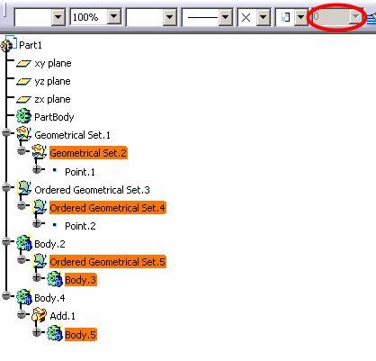
Example 1
All highlighted elements have no layer property since they are sub-bodies. This behavior applies to geometrical sets, ordered geometrical sets and hybrid bodies (whether these hybrid bodies are aggregated by an ordered geometrical set or by a Boolean operator).
Therefore, when any of these elements is selected, the Layer box is grayed out:
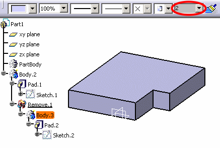
Example 2
Body.3 is an operated solid body (created before V5R14) and as it is operated, its layer property is ignored and cannot be accessed.
The layer property of Body.3 is rerouted to the layer property of the root body, Body.2 in our example:
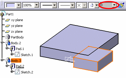
Below is the result when the body is not operated anymore, the body recovers its original own layer property:
About opening existing documents
When opening existing documents (whatever the release level on which they have been created), existing geometry will be migrated to the current layer. To prevent geometry from being assigned to a layer, set the current layer to None before opening existing documents.
Furthermore, if you open existing documents with a current layer set to a layer other than None then close the document without making any changes, you will be prompted to save the document because the geometry was assigned to the current layer when opening the document.
About Version 4 documents
When opening Version 4 documents containing layers, all existing layers
are preserved as is: the layers are stored in the Version 4 document.
Regarding dittos, refer to Layers and Layer
Filters for Dittos.
![]()
