Equipment & Systems Engineering |
Electrical Library |
Creating Electrical ObjectsHow to create an electrical single connector, back shell and mounting equipment |
| Use Case | ||
AbstractThis article discusses the ElecDeviceItf use case. This use case explains how to create an electrical single connector, back shell and mounting equipment with a mechanical part. |
This use case is intended to help you make your first steps in programming with CATIA ELB Interfaces. Its main intent is to allow you to create electrical single connector, back shell or mounting equipment.
[Top]
CAAElecDeviceFactory is a use case of the CAAElecDeviceItf.edu framework that illustrates the CATIA ELB Interfaces framework capabilities.
[Top]
The goal of CAAElecDeviceFactory use case is to show how to create electrical single connector, back shell or mounting equipment and how to define terminations or cavities on the electrical devices created using the appropriate interfaces.
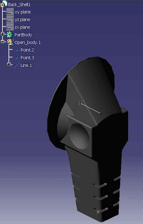
Above is a CATIA image of the back shell geometrical part.
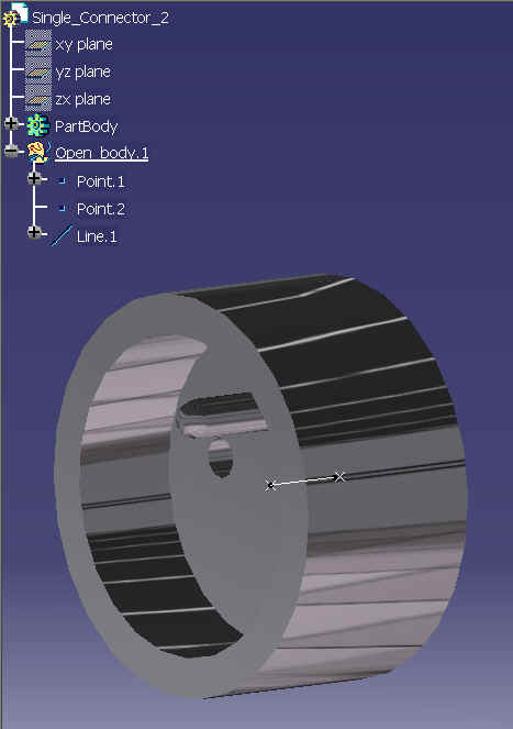
Above is a CATIA image of the single connector geometrical part.
[Top]
To launch CAAElecDeviceFactory, you will need to set up the build time environment, then compile CAAElecDeviceFactory along with its prerequisites, set up the run time environment, and then execute the sample.
To launch the use case, execute the following command:
mkrun -c "CAAElecDeviceFactory input1 input2 input3 input4 input5 output1 output2 output3 output4 output5 output6 output7 "
input2 - the path to the existing external CATPart to be browsed. You may reference the supplied CATPart document called "Single_Connector.CATPart".
input3 - the path to the existing external CATPart to be browsed. You may reference the supplied CATPart document called "Second_SingleConnector.CATPart".
input4 - the path to the existing external CATPart to be browsed. You may reference the supplied CATPart document called "Third_Single_Connector.CATPart".
input5 - the path to the existing external CATPart to be browsed. You may reference the supplied CATPart document called "MountingEquipment.CATPart".
output1 - the path of the file to save in the document "BACK_SHELL.CATPart".
output2 - the path of the file to save in the document "Single_Connector.CATPart".
output3 - the path of the file to save in the document "Second_SingleConnector.CATPart".
output4 - the path of the file to save in the document "Third_Single_Connector.CATPart".
output5 - the path of the file to save in the document "MountingEquipment.CATPart".
output6 - the path of the file to save in the document aggregate under the main document.
output7 - the path of the file to save in the main document.
These documents can be to find in:
InstallRootDirectory\OS\resources\graphic\CAAElecDeviceFactory
where InstallRootDirectory is the root directory of your CAA V5 installation, and OS is a directory the name of which depends on the operating system. Refer to [1] to get the list of the currently supported operating systems and their associated directory names.
[Top]
The CAAElecDeviceFactory sample is made of a single class named CAAElecDeviceFactory located in the CAAElecDeviceFactory.m module of the CAAElecDeviceItf.edu framework:
| Windows | InstallRootDirectory\CAAElecDeviceItf.edu\CAAElecDeviceFactory.m\ |
| Unix | InstallRootDirectory/CAAElecDeviceItf.edu/CAAElecDeviceFactory.m/ |
where InstallRootDirectory is the directory where the CAA CD-ROM
is installed.
This sample deals with the following classes:
| IUnknown | Base Class for the References and Instances |
| CATSessionServices | Class for managing the session |
| CATDocument | Class for the document base class |
| CATDocumentServices | Class for managing document in the session |
| CATIADocument | Class for Representing the document |
| CATIDocRoots | Class for browsing root object in document |
| CATInit | Interface dedicated to define initialisation of a document's data. |
| CATIAlias | Interface dedicated to access the external name of an object |
| CATIProduct | Interface dedicated to define product behaviour |
| CATIPrtPart | Interface dedicated to define to retrieve information on the MechanicalPart feature |
| CATIDescendants | Interface dedicated to to manage ordered components' agregation within a feature |
| CATIGSMPoint | Interface dedicated to define point feature behaviour |
| CATIGSMLine | Interface dedicated to define line feature behaviour |
| CATIEleDocServices | Interface dedicated electrical environment initialisation |
| CATIElbFactory | Interface for extending a product in electrical device such as single connector or back shell or mounting equipment |
| CATIElbSingleConnector | Interface for defining single connector behaviour |
| CATIElbSingleConnectorReferences | Interface for defining single connector reference behaviour |
| CATIElbTermination | Interface for defining electrical termination behaviour |
| CATIElbBackShell | Interface for defining electrical back shell behaviour |
| CATIElbBackShellCnctPt | Interface for defining electrical back shell connection point behaviour |
| CATIElbMountingEquipmentReference | Interface for defining electrical mounting equipment reference behaviour |
| CATIElbConnectorCnctPt | Interface for defining electrical connector connection point behaviour |
| CATIElbCavity | Interface for defining electrical cavity behaviour |
[Top]
We will now first comment the Electrical environment and its components creation by looking at the code of the CAAElecDeviceFactory. There are 17 logical steps in CAAElecDeviceFactory:
| # | Step |
| 1 | Creating the session and a new CATProduct Document |
| 2 | Retrieving the root product of the CATProduct document |
| 3 | Initializing Electrical Environment |
| 4 | Importing the part "Back_Shell.CATPart" under the Root Product |
| 5 | Extending this part in type ElecBackShellE. |
| 6 | Importing the part "SingleConnector.CATPart" under the root product. |
| 7 | Extending this part in Single Connector. |
| 8 | Defining two terminations on the single connector. |
| 9 | Defining a connector connection point on the single connector. |
| 10 | Importing the part "Second_SingleConnector.CATPart". |
| 11 | Defining three cavities on the second single connector. |
| 12 | Importing the part "MountingEquipment.CATPart". |
| 13 | Extending this part in type Mounting Equipment |
| 14 | Defining a cavity on the mounting equipment |
| 15 | Importing the part "Third_Single_Connector.CATPart". |
| 16 | Defining a connector connection point on the single connector. |
| 17 | Epilog |
[Top]
We need a CATSession pointer to create the Session.
... CATSession *pSession = NULL; char *sessionName = "CAA_ElecDeviceFactory_Session"; HRESULT rc = ::Create_Session(sessionName,pSession); ... |
We create a CATDocument pointer with CATDocumentServices class..
...
CATDocument *pMainPrdDoc = NULL;
rc = CATDocumentServices::New("CATProduct", pMainPrdDoc);
...
|
Once the current session has been created, the CATProduct document can be created into the session. pMainPrdDoc is a pointer to this document.
[Top]
We need a CATProduct pointer to retrieve the root product.
...
CATIProduct* piRootProduct = NULL;
CATIDocRoots * pDocRoots = NULL;
rc = pDoc->QueryInterface(IID_CATIDocRoots,(void**) &pDocRoots);
...
CATListValCATBaseUnknown_var* pListRootProduct = pDocRoots->GiveDocRoots();
...
if ( pListRootProduct && pListRootProduct->Size() )
{
  rc = (*pListRootProduct)[1]->QueryInterface(IID_CATIProduct,(void**) &piRootProduct );
}
...
|
[Top]
We initialize the Document by using CATIEleDocServices interface pointer and the method Initialize() on it.
...
CATIEleDocServices * piElecDocServices = NULL;

rc = pMainPrdDoc ->QueryInterface(IID_CATIEleDocServices,(void**) &piElecDocServices );
if ( SUCCEEDED(rc) && piElecDocServices )
{
  rc = piElecDocServices->Initialize();
}
...
|
Initializing the electrical environment is mandatory to enable access to electrical object or electrical attributes.
[Top]
We use a method Import() defined in this sample to import a part from a path on the current session. The method Import() used the method AddExternalComponent of CATIAProduct interfaces to import the part.
... CATDocument* ptDocument = NULL; RC = CATDocumentServices::OpenDocument(PATH, ptDocument, TRUE); ... CATIAProducts_var hRootProducts (ihProductTarget); CATIADocument *pCAADocument = NULL; RC = ptDocument->QueryInterface(IID_CATIADocument, (void **)&pCAADocument); CATIAProduct * pInstantiatedProduct = NULL; RC = hRootProducts->AddExternalComponent(pCAADocument, pInstantiatedProduct); ... RC = pInstantiatedProduct->QueryInterface(CATIProduct::ClassId(), (void**)& oProduct); |
In the sample we import the back shell part as follows:
...
CATIProduct_var hProduct_Level_1 = piRootProduct->AddProduct("Product_Lv1");
 CATIProduct * pProduct_BackShell = NULL;

rc = Import(hProduct_Level_1, PATH_Back_Shell,pProduct_BackShell);
...
RC = pInstantiatedProduct->QueryInterface(CATIProduct::ClassId(), (void**)& oProduct);
|
This sample illustrates the result of importing part
Top]
We need a CATIElbFactory interface pointer to be able to extend the part imported in current session in electrical device with type ElecBackShellE.
... CATIProduct_var hProduct_BackShell_Ref = pProduct_BackShell->GetReferenceProduct(); CATIElbFactory_var hElbFactory(hProduct_BackShell_Ref); rc = hElbFactory -> ExtendPrdAsBackShell() ; ... |
[Top]
The method used for importing SingleConnector.CATPart is identical with Back_Shell.CATPart.
... CATIProduct * pProduct_Single_Connector = NULL; rc = Import(hProduct_Level_1, PATH_Single_Connector,pProduct_Single_Connector); ... |
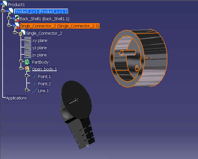
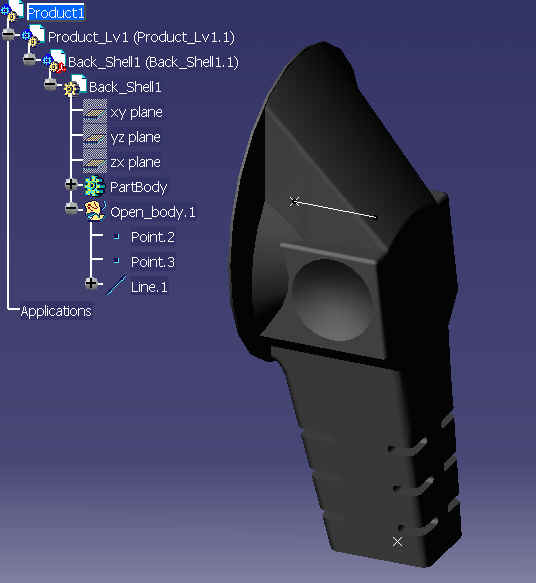
Above is a CATIA image of the import of SingleConnector.CATPart under Product_Lv1.
[Top]
The method ExtendPrdAsSingleConnector() of the interface CATIElbFactory is used to extend the product SingleConnector2 in an electrical single connector.
... CATIProduct_var hProduct_Single_Connector_Ref = pProduct_Single_Connector->GetReferenceProduct(); hElbFactory = hProduct_Single_Connector_Ref; rc = hElbFactory -> ExtendPrdAsSingleConnector() ; ... |
[Top]
To define a termination on a single connector the method AddTermination() of CATIElbSingleConnectorReference is used. The method AddTermination needs for argument the product where the geometry of the single connector was defined and the graphical representation of the geometrical element which defines the termination.
Firstly we find the Product where graphical representation of the single connector is defined as follows:
... CATIProduct * pGeoDefinition_SIC = NULL; rc =hProduct_Single_Connector_Ref-> QueryInterface(IID_CATIProduct,(void**)& pGeoDefinition_SIC); ... |
To find the geometrical element of the single connector such as points "Point.1" or "Point.2" defined in its open body we use the following method:
First, we retrieve the part of the single connector:
... CATILinkableObject_var hLinkable_SIC (hProduct_Single_Connector_Ref); CATDocument * pDocOfPart_SIC = hLinkable_SIC->GetDocument(); ... CATIContainer_var hPart_SIC_RootContainer =pPart_SIC_RootContainer; pPart_SIC_RootContainer ->Release(); CATIPrtContainer_var hPartContainer_SIC = hPart_SIC_RootContainer; CATIPrtPart_var hPart_SIC = hPartContainer_SIC->GetPart(); ... |
The first point "Point.1" defined in the Openbody of the part is retrieved using a locally method named FindInPart()
... CATBaseUnknown * pPointOnSIC = NULL; rc = FindInPart(hPart_SIC,IID_CATIGSMPoint,"Point.1",pPointOnSIC); ... |
The method FindInPart returns an entity which is defined in the part, with argument an instance name of element we are looking for and the unique identifier of the interface.
...
CATIDescendants_var hDescendant(hPart);
CATListValCATISpecObject_var  hElementlist;
hDescendant->GetAllChildren(CATISpecObject::ClassName(), hElementlist);
...
int Taille_ElementList = hElementlist.Size() ;
for (int i=1; i<=Taille_ElementList ; i++)
{
  CATBaseUnknown * ptInternalPtr = NULL;
  CATIAlias_var hAlias ( hElementlist[i]);
  ...
  hElementlist[i]->QueryInterface (iIID, (void**)& ptInternalPtr);
  ...
  if (hAlias->GetAlias() == InstanceName)
  {
    RC = ptInternalPtr->QueryInterface(CATBaseUnknown::ClassId(), (void**)& oEntity);
    if(SUCCEEDED(RC) && oEntity)
    {
      ptInternalPtr->Release();
       break;
    }
    else
    {
      RC = E_FAIL;
      ptInternalPtr->Release();
      return RC;
    }
  }
  ptInternalPtr->Release();
  ...
}
...
|
Then we find the graphical representation of the point:
... CATILinkableObject * ptRepresentationOfPoint_SIC = NULL; rc = pPointOnSIC->QueryInterface(CATILinkableObject::ClassId(), (void**)& ptRepresentationOfPoint_SIC); ... |
Finally, we create the termination:
...
CATIElbSingleConnectorReference_var hSingleConnectorRefer(hProduct_Single_Connector_Ref);
...
CATUnicodeString Id_Number = "Termination_01";
int iPositionNumber = 0;
CATIElbTermination * pElbTermination = NULL;
rc = hSingleConnectorRefer->AddTermination(Id_Number,
                                              iPositionNumber,
                                              pGeoDefinition_SIC,
                                              ptRepresentationOfPoint_SIC,
                                              pElbTermination);
...
|
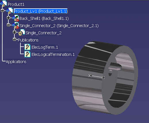
The connector connection point is created using the services AddConnectorCnctPt of CATIElbSingleConnector interfaces as follows:
CATIElbSingleConnector * pElbSIC = NULL;
rc = pProduct_Single_Connector->QueryInterface(IID_CATIElbSingleConnector,(void**)& pElbSIC);

CATUnicodeString JointType = "ConnectorCnctPt";
Id_Number = "ConnectorCnctPt_01";
CATIElbConnectorCnctPt * pElbCntrCnctPt = NULL;

rc = pElbSIC->AddConnectorCnctPt(Id_Number,
                                    pProduct_Single_Connector,
                                    ptRepresentationOfPoint_SIC,
                                    JointType,
                                    pListJointReferenceFirstSIC,
                                    pElbCntrCnctPt);
|
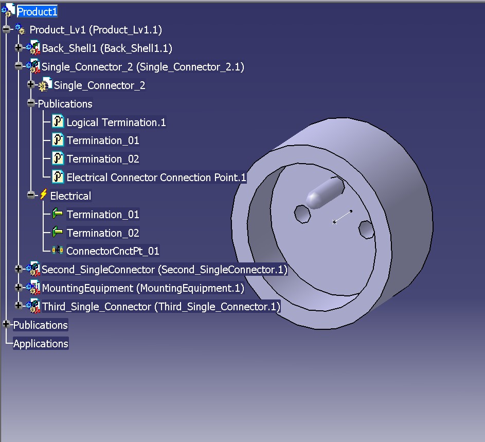
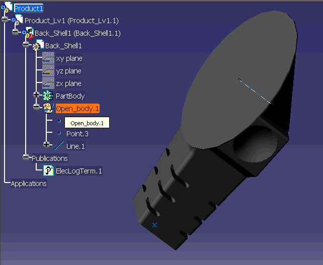
Above is a CATIA image of the result of our study.
[Top]
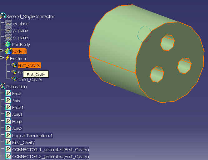
The part "Second_SingleConnector.CATPart" is imported using the local method FindInPart() as follows:
... CATIProduct * pProduct_Second_SIC= NULL; rc = Import(hProduct_Level_1, PATH_Second_SIC,pProduct_Second_SIC); ... |

Above is a CATIA image of the second single connector part.
Firstly we retrieve the list of published geometry using the methods of CATIPrdObjectPublisher interface. This geometry is then used to create the cavity.
CATIPrdObjectPublisher * pPrdObjectPublisher = NULL;
rc = hProductSecondSICRef->QueryInterface(IID_CATIPrdObjectPublisher,(void**)&pPrdObjectPublisher);
....
CATListValCATUnicodeString * pListOfPublications = NULL;
int hasPublication = pPrdObjectPublisher->ListPublications(pListOfPublications);

CATBaseUnknown * P_PublicationGeometrique=NULL;
CATUnicodeString SubPublication;
int i=0;
int result = 0;>
for( i=1;i<=2;i++)
{
  result = pPrdObjectPublisher->GetDirectObject ((*pListOfPublications)[i],
                                                    P_PublicationGeometrique,
                                                    SubPublication);
}
|
The cavity is created using the method AddCavity() of CATIElbSingleConnectorReference interface as follows:
if(i==1) P_PublicationGeometrique->QueryInterface(IID_CATILinkableObject,(void**)&pRepresentation); ... CATUnicodeString ID_NUMBER = "First_Cavity"; int Number = 0; CATIElbCavity * pElbCavity = NULL; rc = pElecRefSecondSIC->AddCavity(ID_NUMBER, Number, pGeoDefinition,pRepresentation,pListJointReference,pElbCavity); |
The part "MountingEquipmentr.CATPart" is imported using the local method FindInPart() as follows:
... CATIProduct * pProduct_MountingEqt = NULL; rc = Import(hProduct_Level_1, PATH_MountingEqt,pProduct_MountingEqt); ... |

Above is a CATIA image of the mounting equipment part.
We need the method ExtendPrdAsMountingEquipment() of the interface CATIElbFactory to extend the product in mounting equipment.
... CATIProduct_var hProduct_MountingEqt_Ref = pProduct_MountingEqt->GetReferenceProduct(); hElbFactory = hProduct_MountingEqt_Ref; rc = hElbFactory -> ExtendPrdAsMountingEquipment() ; ... |
Firstly we retrieve the list of published geometry using the methods of CATIPrdObjectPublisher interface and we use this geometry to create the cavity:
rc = hProduct_MountingEqt_Ref->QueryInterface(IID_CATIPrdObjectPublisher,(void**)&pPrdObjectPublisher);
...
hasPublication = pPrdObjectPublisher->ListPublications(pListOfPublications);
for ( i=1; i<=2; i++)
{
  result = pPrdObjectPublisher->GetDirectObject ((*pListOfPublications)[i],
                                                  P_PublicationGeometrique,
                                                  SubPublication);
}
|
The cavity is created using the services AddCavity() of CATIElbMountingEquipmentReference interface as follows:
if(i==1) P_PublicationGeometrique->QueryInterface(IID_CATILinkableObject,(void**)&pRepresentation); ... Id_Number = "First_Cavity"; JointType = "Cavity"; int Number = 0; CATIElbCavity * pElbCavity = NULL; rc = pElecRefMountingEqt->AddCavity(ID_NUMBER, Number, pGeoDefinition,pRepresentation,pListJointReference,pElbCavity); |
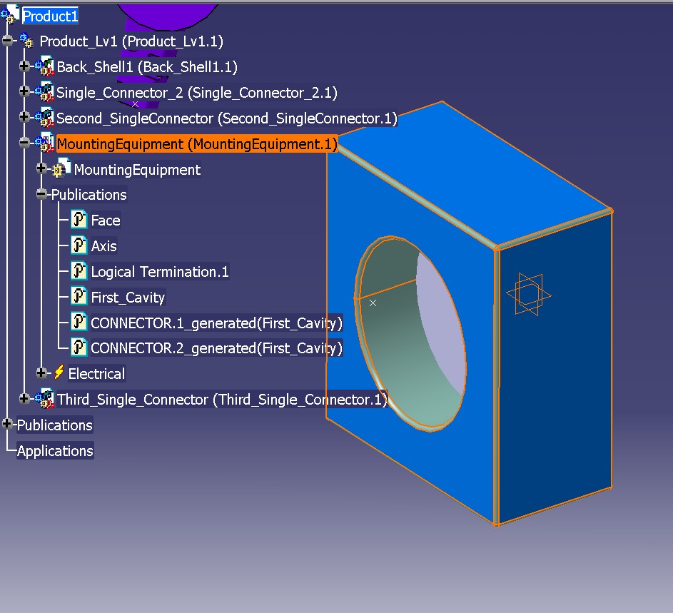
Above is a CATIA image of the mounting equipment part after the creation of the cavity.
The part "Third_Single_Connector.CATPart" is imported using the local method FindInPart() as follows:
... CATIProduct * pProduct_Third_SIC= NULL; rc = Import(hProduct_Level_1, PATH_Third_SIC,pProduct_Third_SIC); ... |
The connector connection point is created using the method AddConnectorCnctPt of CATIElbSingleConnector interface as follows:
CATIElbSingleConnector * pElbThirdSIC = NULL;
rc = pProduct_Single_Connector->QueryInterface(IID_CATIElbSingleConnector,(void**) & pElbThirdSIC);

JointType = "ConnectorCnctPt";
Id_Number = "First_ConnectorCnctP";
CATIElbConnectorCnctPt * pElbConnectorCnctPt = NULL;

rc = pElbSIC->AddConnectorCnctPt(Id_Number,
                                    pProduct_Third_SIC,
                                    pRepresentation,
                                    JointType,
                                    pListJointReferenceThirdSIC,
pElbConnectorCnctPt); |
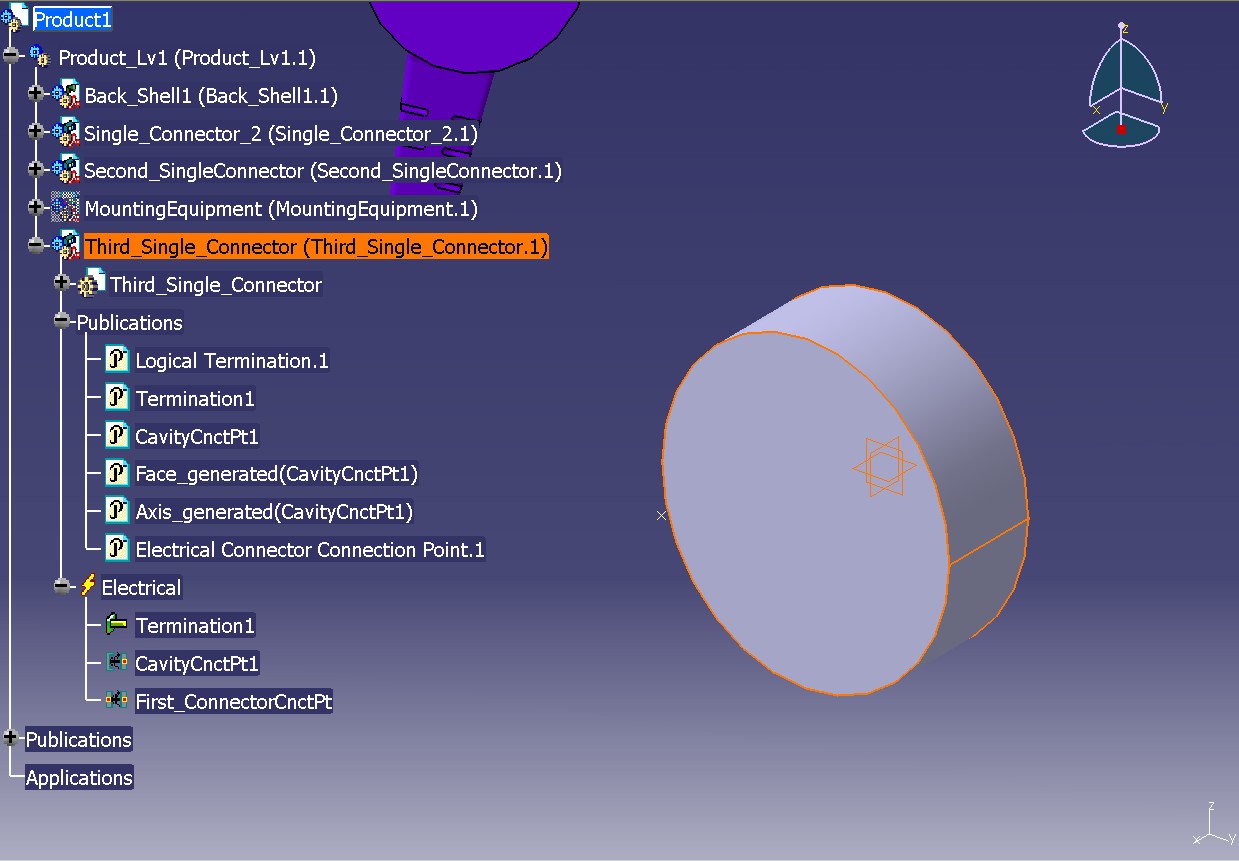
Above is a CATIA image of the third single connector after the creation of the connector connection point (the mounting equipment is in no-show).
Removing document from session and closing the session.
CATBoolean iSavePointedIfNecessary = TRUE;
rc = CATDocumentServices::SaveAs ( *pDocOfPart_BackShell,argv[6],".CATPart",iSavePointedIfNecessary );
rc = CATDocumentServices::SaveAs ( *pDocOfPart_SIC,argv[7],".CATPart",iSavePointedIfNecessary );
rc = CATDocumentServices::SaveAs ( *pDocOfPart_SecondSIC,argv[8],".CATPart",iSavePointedIfNecessary ); rc = CATDocumentServices::SaveAs ( *pDocOfPart_ThirdSIC,argv[9],".CATPart",iSavePointedIfNecessary ); rc = CATDocumentServices::SaveAs ( *pDocOfPart_MountingEqt,argv[10],".CATPart",iSavePointedIfNecessary ); rc = CATDocumentServices::SaveAs ( *pDoc_Level_1,argv[11],".CATProduct",iSavePointedIfNecessary ); rc = CATDocumentServices::SaveAs ( *pMainPrdDoc,argv[12],".CATProduct",iSavePointedIfNecessary ); ... rc = CATDocumentServices::Remove(*pDoc); rc = ::Delete_Session(sessionName); ... |
[Top]
This use case has demonstrated the way to create electrical devices in a document such as single connector, back shell or mounting equipment, and how adding electrical connectors on these devices such as terminations, cavities or connector connection points.
[Top]
| [1] | Building and Launching a CAA V5 Use Case |
| [Top] | |
| Version: 1 [March 2003] | Document created |
| [Top] | |
Copyright © 2003, Dassault Systèmes. All rights reserved.