Mechanical Design |
Drafting |
Creating Frames and Title Blocks in a CATDrawing DocumentHow to create drawing geometry and annotations |
| Use Case | ||
AbstractThis article discusses the CAADrwTitleBlock use case. This use case explains how to read a CATDrawing document, get the sheet background view, and create geometry and annotations in it. |
This use case is intended to show you how to navigate through drawing sheets and views as well as how to get and use geometrical and annotation factories.
[Top]
CAADrwTitleBlock is a use case of the CAADraftingInterfaces.edu framework that illustrates DraftingInterfaces framework capabilities.
[Top]
|
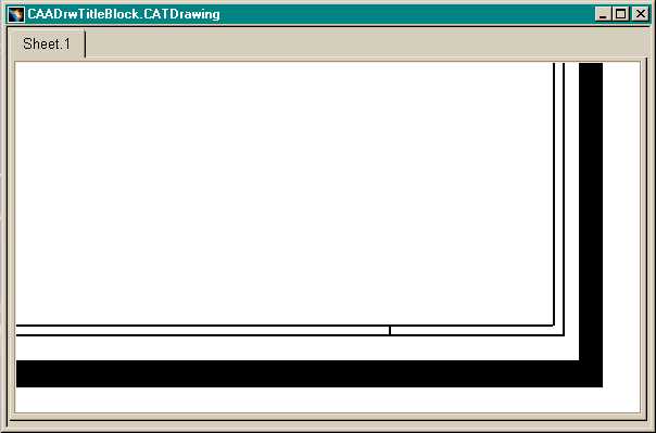
Fig. 1 represents the CATDrawing document on which a title block will be added. This document is not provided with the use case.
 |
Fig. 2 represents the CATDrawing document modified by the use case program. It first creates a basic drafting structure composed of a drawing, a sheet, and two superimposed views.
The two views are:
These two views are part of the sheet. So they cannot be deleted and they are not shown in the graph. Then the program gets the background view and creates a frame using 2D lines and a text in the bottom right corner.
[Top]
To launch CAADrwTitleBlock, you will need to set up the build time environment, then compile CAADrwTitleBlock along with its prerequisites, set up the run time environment, and then execute the use case [1].
When you launch the use case, pass the full pathname of the file into which you you want to store the created document as argument.
e:> mkrun -c cmd CAADrwTitleBlock c:\DrawingTest.CATDrawing c:\DrawingTestwithtitleblocks.CATDrawing |
$ mkrun -c cmd CAADrwTitleBlock /u/users/DrawingTest.CATDrawing /u/users/DrawingTestwithtitleblocks.CATDrawing |
[Top]
The CAADrwTitleBlock use case is made of a single source file named CAADrwTitleBlock.cpp located in the CAADrwTitleBlock.m module of the CAADraftingInterfaces.edu framework:
| Windows | InstallRootDirectory\CAADraftingInterfaces.edu\CAADrwTitleBlock.m\ |
| Unix | InstallRootDirectory/CAADraftingInterfaces.edu/CAADrwTitleBlock.m/ |
where InstallRootDirectory is the directory where the CAA CD-ROM
is installed.
[Top]
There are six steps in CAADRWTitleBlock:
[Top]
int main(int    iArgc,   // Number of arguments (1)
         char** iArgv)   // Path to the new *.CATDrawing document
{
  // Check arguments
  if(3 != iArgc) return 1;
  const char *fileName = iArgv[1];
  const char *fileNameOut = iArgv[2];

  // CREATE  SESSION
  // ==================

  CATSession *pSampleSession = NULL;
  HRESULT hr = ::Create_Session("SampleSession",pSampleSession);
  if (FAILED(hr)) return 1;
...
|
This section represents the usual sequence for creating a CATIA document [2].
[Top]
...
  CATDocument* pDoc = NULL;
  if (!SUCCEEDED(CATDocumentServices::OpenDocument(fileName, pDoc)))
  {
    // Ends session
    ::Delete_Session("SampleSession");
    return 2;
  }
  // Gets the drawing feature using the CATIDftDocumentServices interface
  CATIDrawing *piDrawing = NULL;
  CATIDftDocumentServices *piDftDocServices = NULL;
  if (SUCCEEDED(pDoc->QueryInterface(IID_CATIDftDocumentServices, (void **)&piDftDocServices)))
  {
    piDftDocServices->GetDrawing(IID_CATIDrawing, (void **)&piDrawing);
    piDftDocServices->Release();
  }

  if (NULL == piDrawing)
    return 1;
...
|
The root feature of a drawing document is the Drawing, that is, the feature
that implements the CATIDrawing interface. We can get a pointer to CATIDrawing
using the CATIDftDocumentServices interface, which is implemented by the
document. The GetDrawing method first argument is the CATIDrawing
interface IID.
[Top]
... // We can get the current sheet CATISheet_var spSheet = piDrawing->GetCurrentSheet(); // And the sheet background view CATIView_var spBgView = spSheet->GetBackgroundView(); // Memory cleaning piDrawing->Release(); ... |
A drawing may contain several sheets, but only one is current at a time. The current sheet is the sheet containing the active view, that is the view currently edited. The methods of the CATISheet and CATIView interfaces do return handlers, so we don’t need to care about releasing them. The drawing variable is a pointer to CATIDrawing, so we have to release when it's no longer used.
[Top]
...
  // GEOMETRY CREATION
  // =================

  // We now can create geometries in the view after :
  //   - Setting the view as the current one
  //   - Getting the view geometry factory interface
  spSheet->SetCurrentView(spBgView);
  CATI2DWFFactory_var spGeomFactory = spBgView;

  double X[8] = { 936.0, 949.0, 963.0, 1010.0, 1062.0, 1093.0, 1157.0, 1176.0};
  double Z[11] ={ 17.0, 22.0, 35.0, 48.0, 53.0, 58.0, 63.0, 68.0, 73.0, 78.0, 88.0};
  double PtTmp[6];

  double startPoint[2], endPoint[2];

  // Creation of horizontal lines
  PtTmp[0]=Z[0];
  PtTmp[1]=Z[1];
  PtTmp[2]=Z[3];
  PtTmp[3]=Z[5];
  PtTmp[4]=Z[7];
  PtTmp[5]=Z[10];
  for (int i= 0;i < 6; i++)
  {
    startPoint[0] = X[0];
    startPoint[1] = PtTmp[i];
    endPoint[0] = X[7];
    endPoint[1] = PtTmp[i];
    spGeomFactory->CreateLine(startPoint, endPoint);
  }
  startPoint[0] = X[3];
  startPoint[1] = Z[2];
  endPoint[0] = X[7];
  endPoint[1] = Z[2];
  spGeomFactory->CreateLine(startPoint, endPoint);

  startPoint[0] = X[0];
  startPoint[1] = Z[9];
  endPoint[0] = X[5];
  endPoint[1] = Z[9];
  spGeomFactory->CreateLine(startPoint, endPoint);

  PtTmp[0]=Z[4];
  PtTmp[1]=Z[6];
  PtTmp[2]=Z[8];
  for (i= 0;i < 3; i++)
  {
    startPoint[0] = X[3];
    startPoint[1] = PtTmp[i];
    endPoint[0] = X[5];
    endPoint[1] = PtTmp[i];
    spGeomFactory->CreateLine(startPoint, endPoint);
  }

  // Creation of vertical lines
  PtTmp[0]=X[0];
  PtTmp[1]=X[7];
  for (i= 0;i < 2; i++)
  {
    startPoint[0] = PtTmp[i];
    startPoint[1] = Z[0];
    endPoint[0] = PtTmp[i];
    endPoint[1] = Z[10];
    spGeomFactory->CreateLine(startPoint, endPoint);
  }

  startPoint[0] = X[3];
  startPoint[1] = Z[1];
  endPoint[0] = X[3];
  endPoint[1] = Z[10];
  spGeomFactory->CreateLine(startPoint, endPoint);

  startPoint[0] = X[5];
  startPoint[1] = Z[3];
  endPoint[0] = X[5];
  endPoint[1] = Z[10];
  spGeomFactory->CreateLine(startPoint, endPoint);

  PtTmp[0]=X[4];
  PtTmp[1]=X[6];
  for (i= 0;i < 2; i++)
  {
    startPoint[0] = PtTmp[i];
    startPoint[1] = Z[1];
    endPoint[0] = PtTmp[i];
    endPoint[1] = Z[2];
    spGeomFactory->CreateLine(startPoint, endPoint);
  }

  startPoint[0] = X[1];
  startPoint[1] = Z[5];
  endPoint[0] = X[1];
  endPoint[1] = Z[7];
  spGeomFactory->CreateLine(startPoint, endPoint);
  startPoint[0] = X[2];
  startPoint[1] = Z[5];
  endPoint[0] = X[2];
  endPoint[1] = Z[9];
  spGeomFactory->CreateLine(startPoint, endPoint);

  //  Lines and circles creation for projection mode symbol.
  double X1[3] = { 941.0, 949.0, 955.0};
  double Z1[5] ={ 70.0, 71.0, 73.0, 75.0, 76.0};
  startPoint[0] = X1[0];
  startPoint[1] = Z1[1];
  endPoint[0] = X1[0];
  endPoint[1] = Z1[3];
  spGeomFactory->CreateLine(startPoint, endPoint);

  startPoint[0] = X1[0];
  startPoint[1] = Z1[3];
  endPoint[0] = X1[1];
  endPoint[1] = Z1[4];
  CATISpecObject_var Line1 = spGeomFactory->CreateLine(startPoint, endPoint);

  startPoint[0] = X1[1];
  startPoint[1] = Z1[4];
  endPoint[0] = X1[1];
  endPoint[1] = Z1[0];
  spGeomFactory->CreateLine(startPoint, endPoint);

  startPoint[0] = X1[1];
  startPoint[1] = Z1[0];
  endPoint[0] = X1[0];
  endPoint[1] = Z1[1];
  CATISpecObject_var Line2 = spGeomFactory->CreateLine(startPoint, endPoint);

  // Creation of two concentric circles:
  double center[2];
  center[0]=X1[2];
  center[1]=Z1[2];
  double radius = 3.0;
  CATISpecObject_var Cercle1 = spGeomFactory->CreateCircle(center,radius);

  radius = 2.0;
  spGeomFactory->CreateCircle(center,radius);
...
|
Before using the factory, you have to make the view current. The view implements the CATI2DWFFactory 2D geometry factory interface. It is the sketcher factory and, as a consequence, you can use the same methods to create a profile in a part or 2D geometric objects in a drawing view.
[Top]
...
  // DRESSUP CREATION
  // ================

  // Gets the view annotation factory
  CATIDrwAnnotationFactory_var spAnnFactory = spBgView;

  // Texts creation
  CATIDftText *piDftText = NULL;
  const double txtpos1[2] = {1013.,45.};
  if (SUCCEEDED(spAnnFactory->CreateDftText(txtpos1,&piDftText)))
  {
    // Set String
    CATUnicodeString textString("TITLE BLOCK PERFORMED BY CAA2 APPLICATION");
    wchar_t *ptxtChar = new wchar_t[textString.GetLengthInChar()+1];
    textString.ConvertToWChar(ptxtChar);
    piDftText->SetString(ptxtChar);
    delete [] ptxtChar;
    ptxtChar = NULL;
    // Text properties modification: Set bold and italic
    CATIDftTextProperties *piDftTextProp = NULL;
    if (SUCCEEDED(piDftText->GetTextProperties(&piDftTextProp)))
    {
      piDftTextProp->SetBold(TRUE);
      piDftTextProp->SetItalic(TRUE);

      piDftTextProp->Release();piDftTextProp=NULL;
    }
    piDftText->Release();piDftText=NULL;
  }
  const double txtpos2[2] = {940., 40.};
  if (SUCCEEDED(spAnnFactory->CreateDftText(txtpos2,&piDftText)))
  {
    // Set String
    CATUnicodeString textString("DASSAULT \nSYSTEMES");
    wchar_t *ptxtChar = new wchar_t[textString.GetLengthInChar()+1];
    textString.ConvertToWChar(ptxtChar);
    piDftText->SetString(ptxtChar);
    delete [] ptxtChar;
    ptxtChar = NULL;
    CATIDftTextProperties *piDftTextProp = NULL;
    // Text properties modification: Set bold and italic
    if (SUCCEEDED(piDftText->GetTextProperties(&piDftTextProp)))
    {
      piDftTextProp->SetBold(TRUE);
      piDftTextProp->SetItalic(TRUE);
      piDftTextProp->Release();piDftTextProp=NULL;
    }
    piDftText->Release();piDftText=NULL;
  }
  const double txtpos3[2] = {940., 54.};
  if (SUCCEEDED(spAnnFactory->CreateDftText(txtpos3,&piDftText)))
  {
    // Set String
    CATUnicodeString textString("Date : 07 - 31 - 2000");
    wchar_t *ptxtChar = new wchar_t[textString.GetLengthInChar()+1];
    textString.ConvertToWChar(ptxtChar);
    piDftText->SetString(ptxtChar);
    delete [] ptxtChar;
    ptxtChar = NULL;
    // Text properties modification: Set bold and italic
    CATIDftTextProperties *piDftTextProp = NULL;
    if (SUCCEEDED(piDftText->GetTextProperties(&piDftTextProp)))
    {
      piDftTextProp->SetBold(TRUE);
      piDftTextProp->SetItalic(TRUE);

      CATIDrwSubString *piDrwSubString = NULL;
      if (SUCCEEDED(piDftText->QueryInterface(IID_CATIDrwSubString,(void **)&piDrwSubString)))
      {
        // Select the sub string to modifiable.
        piDrwSubString->SetSelection(1,21);
        piDftTextProp->SetFontSize(3.5);
        piDrwSubString->Release();piDrwSubString=NULL;
      }
      piDftTextProp->Release();piDftTextProp=NULL;
    }
    piDftText->Release();piDftText=NULL;
  }
// axis line and center line creation CATIDrwAxisLine_var axisline = spAnnFactory->CreateDrwAxisLine(Line1,Line2); CATIDrwCenterLine_var centerline = spAnnFactory->CreateDrwCenterLine(Cercle1); ... |
The CATIDrwAnnotationFactory annotation factory is implemented by the
view and so the coordinates passed in CreateDrwText are view
coordinates. The CATIDrwTextProperties interface allows for text property
modification, such as setting the text with a bold typeface using the SetBold
method.
[Top]
...
  // Save the result
  rc = CATDocumentServices::SaveAs(*pDoc, (char *)fileName);
  ... // Check rc
  rc = CATDocumentServices::Remove (*pDoc);
  ... // Check rc
  // Ends session and drops document
  rc = ::Delete_Session("SampleSession");
  ... // Check rc

  return 0;
}
|
This section represents the usual sequence for saving a newly created CATIA document [2].
[Top]
This use case shows the objects and interfaces used when creating a
CATDrawing document, and when creating a frame and a title block in the current
sheet background view. The CATIDrawing interface is implemented by the
drawing root object. A pointer to this interface is the key to enter and
navigate the drawing structure, and can be retrieved using the GetDrawing
method of the CATIDftDocumentServices interface implemented by the
document. Retrieving the background view is performed first by retrieving the
current sheet thanks to the GetCurrentSheet method of the CATIDrawing
interface, and then asking the current sheet for this background view using the GetBackgroundView
of CATISheet. This background view is made current using the SetCurrentView
method of CATISheet, and a handler to the CATI2DWFFactory
interface implemented by the view is retrieved to create the frame lines thanks
to the CreateLine method. The view also implements the CATIDrwAnnotationFactory
interface and the title block is created using its CreateDrwText
method, and set with a bold typeface using the SetBold method.
[Top]
| [1] | Building and Lauching CAA V5 Samples |
| [2] | Creating a New Document |
| [Top] | |
| Version: 1 [Jan 2000] | Document created |
| [Top] | |
Copyright © 2000, Dassault Systèmes. All rights reserved.