Analysis Solution |
Analysis Modeler |
Creating Analysis Features - Part 4How to create some specific images for a physical type |
| Use Case | ||
AbstractThis article accompanies the Analysis New Feature Overview technical article. It explains how to create an image based on the physical types that are provided by the CATICharacCollector implementation of the Aerodynamic solution Set. |
This use case is intended to help you program a command that display specific analysis results. Refer to the Reference [1] and [3] to be familiar to the prerequisite.
[Top]
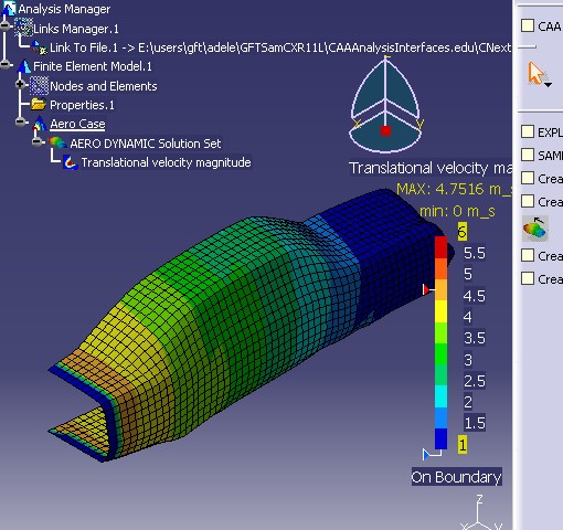
The goal of this Use Case is to create a command that will produce the following image.

[Top]
To launch this use case, you will need to set up the build time environment, then compile CAAAniWB and CAAAniAeroDTransition along with its prerequisites, set up the run time environment, and then execute the use case [2].
[Top]
The use case is made of classes located in the CAAAniWB.m and CAAAniAeroDTransition.m modules of the CAAAnalysisInterfaces.edu framework:
| Windows | InstallRootDirectory\CAAAnalysisInterfaces.edu\CAAAniWB.m\ |
InstallRootDirectory\CAAAnalysisInterfaces.edu\CAAAniAeroDTransition.m\ |
|
| Unix | InstallRootDirectory/CAAAnalysisInterfaces.edu/CAAAniWB.m/ |
InstallRootDirectory/CAAAnalysisInterfaces.edu/CAAAniAeroDTransition.m/ |
where InstallRootDirectory is the directory where the CAA CD-ROM
is installed.
The following table shows which code resources are used in this Use Case. These resources are physically located within the appropriate directories (with same names) of your CAA installation.
| Framework | Module/Interface | Source | Content |
|---|---|---|---|
|
CAAAnalysisInterfaces.edu |
CAAAniWB.m |
CAAAniCreateOneImageCmd.cpp |
Image creation command |
[Top]
We will now comment each of those steps by looking at the code. The objective is to define a command. Note the associated resources: the icon is defined as I_VelocitySmooth.bmp and the NLS message file is CAAAniCreateOneImageCmd.CATNls. This command is included in the headers definition of the ANICgf workbench.
Two data members are defined:
...#include "CATCreateExternalObject.h"
CATCreateClass(CAAAniCreateOneImageCmd);

//=============================================================================
// Implementation
//=============================================================================
CATImplementClass( CAAAniCreateOneImageCmd ,
                   Implementation ,
                   CATStateCommand ,
                   CATNull );

//=============================================================================
// constructor
//=============================================================================
CAAAniCreateOneImageCmd::CAAAniCreateOneImageCmd ():
  CATStateCommand(CATString("CAAAniCreateOneImageCmd")),
  _SolutionFound (NULL),
  _Solution (NULL)
{}
...
|
The "BuildGraph" method defines a single state command. As soon the appropriate feature is selected, the image creation is called:
...
AddTransition (selState,NULL,IsOutputSetCondition(_SolutionFound) ,
         Action ((ActionMethod) &CAAAniCreateOneImageCmd::CreateImage,NULL));
...
|
[Top]
The post-processing container implements CATISamImageFactory interface for image creation. The image is associated to it's name, here "CAA_Translational_velocity_Iso" that is customized in the CAAAniImage.xml file.
...
  CATISamImageFactory * piFactory = NULL;
  hr = piContainer -> QueryInterface (IID_CATISamImageFactory,(void **) &piFactory);
  piContainer -> Release(); piContainer = NULL;

  if (NULL == piFactory) return TRUE; /* quit the command in case of error */

  // image creation
  CATString imageName ("CAA_Translational_velocity_Iso");
  CATISamImage * piNewImage = NULL;
  hr = piFactory -> CreateImage (imageName,_Solution,piNewImage);
  piFactory -> Release(); piFactory = NULL;
  if (NULL == piNewImage) return TRUE; /* quit the command in case of error */
  piNewImage -> Release ();  piNewImage = NULL;
...
|
Now, we will customize the associated color map. The value for the minimum and maximum display are fixed.
...
  // we retrieve the color map
  CATISamImageColorMap * piColorMap = NULL;
  hr = piNewImage -> GetColorMap(piColorMap);
  if (NULL != piColorMap)
  {
    // we impose the bounds
    piColorMap -> ImposeMinValue(1.f);
    piColorMap -> ImposeMaxValue(6.f);

    // and we update the color map...
    piColorMap -> UpdateDisplay();

    piColorMap -> Release (); piColorMap = NULL;
  }
...
|
[Top]
This use case can be used as an example create images based on the physical types that are computed by your feature.
[Top]
| [1] | Analysis Images Overview |
| [2] | Building and Launching a CAA V5 Use Case |
| [3] | 3D PLM Enterprise Architecture |
| [Top] | |
| Version: 1 [Apr 2000] | Document created |
| [Top] | |
Copyright © 2000, Dassault Systèmes. All rights reserved.