Creating a Triangle with rounded corners using constraints
To create a shape with constraints and rounded corners, you will need to create the spParamDictionary, spGSMFactory, spParmFactory and spPrtFactory Factories. The method discussed here can be applied to create any desired shape.
To Create a triangle with rounded corners:
1) Create 3 points (See Creating a Point in CAA RADE)
2) Create 3 Lines between the points (See Creating a Line CAA RADE)
3) Create a support plane from the three points using the following code:
CATIGSMPlane3Points_var Supportplane = spGSMFactory->CreatePlane(spPoint1,
                                                                 spPoint2,
                                                                 spPoint3);
CATISpecObject_var spSupportplane = Supportplane;
This support plane is used when creating the radius between each line.
4) For each different radius, create a radius parameter using the following code:
CATICkeParm_var Radius1 = NULL_var;
CATICkeMagnitude_var spRadMag = spParamDictionary->FindMagnitude("LENGTH");
CATUnicodeString name("Radius 1");
Radius1 = spParmFactory->CreateDimension(spRadMag,
                                         name,
                                         .01);  // .01 is the magnitude of the radius
5) To create the radius on each corner, use the following code:
CATIGSMCorner_var Corner1 = spGSMFactory->CreateCorner(spLine1,
                                                      spLine2,
                                                      spSupportplane,
                                                      Radius1,
                                                      CATGSMSameOrientation,
                                                      CATGSMSameOrientation,
                                                      FALSE);
CATISpecObject_var spCorner1 = Corner1;
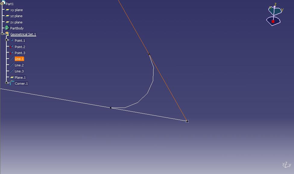
6) Next we create a split on each end of each line in order to trim the excess geometry. We need to do this again to the split object.
CATIGSMSplit_var Split1 = spGSMFactory->CreateSplit(spLine1,
                                                   spRadius1,
                                                   CATGSMSameOrientation);
CATISpecObject_var spSplit1 = Split1;

CATIGSMSplit_var Split1a = spGSMFactory->CreateSplit(spSplit1,
                                                     spRadius3,
                                                     CATGSMInvertOrientation);
CATISpecObject_var spSplit1a = Split1a;
For some of the end points you may need to switch the last parameter of CreateSplit() between CATGSMSameOrientation and CATGSMInvertOrientation.
7) Once you have your three lines split, you need to join them into a single shape object. To do this, first we need to add each of the final split lines and radius' (six total objects) to a list.
CATLISTV(CATISpecObject_var) joincurves;
joincurves.Append(spSplit1a);
joincurves.Append(spSplit2a);
joincurves.Append(spSplit3a);
joincurves.Append(spRadius1);
joincurves.Append(spRadius2);
joincurves.Append(spRadius3);
8) Before we join the curves, we also need to create a Merge Distance object.
CATICkeParm_var Mergedist = NULL_var;
CATICkeMagnitude_var spMergedist = spParamDictionary->FindMagnitude("LENGTH");
CATUnicodeString mergename("Merge Distance");
Mergedist = spParmFactory->CreateDimension(spMergedist,
                                           mergename,
                                           .0001);
9) Now we can join this list of objects into a single shape and insert it into the part.
CATIGSMAssemble_var CurveAssy = spGSMFactory->CreateAssemble(joincurves,
                                                             Mergedist,
                                                             FALSE);
CATISpecObject_var spCurveAssy = CurveAssy;

spCurveAssy->Update();
CATIGSMProceduralView_var spCurObj = Curveassembly;
spCurObj->InsertInProceduralView();
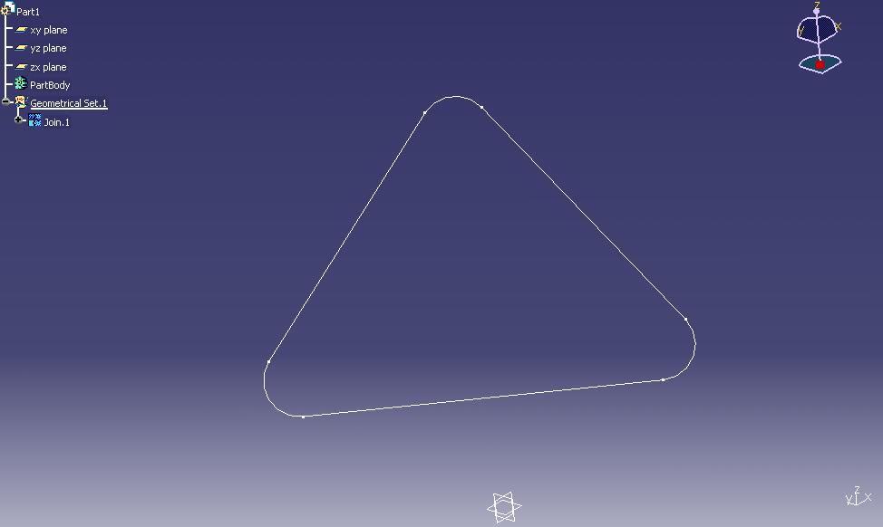
Any of these parameters can now be edited in the Part Tree.