Understanding Connection Types
|
|
The different types of connections that you see in a design document are listed here. These connections are selected by the application, based on the action you take, such as when you route from the end of a run. The images below show the symbols used for each type of connection. | |
|
|
1. |
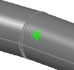
Star connection: This connection is used when you route a new
route from the end of an existing route. An "equal" relationship is
created between the two segments. If you move one route the other
route will follow it. Note that only the connected end moves. If the
segment is not long enough to maintain the connection then it will be
lengthened.
|
| 2. |
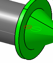
Master-slave connection: As
the name denotes, a master-slave connection is established between
the two objects. This is created when you branch from a run - the
branch is the slave and the existing run becomes the master. The
branch will move if you move the master. When you place a part on a
run the part becomes the master and the run will move if you move
the part. If necessary the run will become longer.
|
|
| 3. |
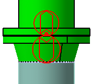
Cross document connection:
A cross document connection is established when a connection is
created between two objects in different work packages. The
connectors should be published. To view these connections in a
design, click Analyze - Cross Document Connections. See
Using Work Packages for more
information.
|
|
| 4. |
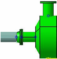
Fluidic part connection:
These connections are used when you connect two parts that are used
in fluidic situations, such as a flange to a bendable pipe.
|
|
![]()


