Creating a Run Using a Schematic
|
|
This task shows how to create a run using a schematic drawing. | |
|
|
Beginning Release 15, 3-D versions of runs must be associated with the corresponding schematic, if you want to do schematic driven parts placement on a run. Runs will automatically be associated if you create them in Release 15 using a schematic. Runs that are not associated with the corresponding schematic must be associated by you, if you want schematic driven parts placement. See Analyzing Schematic Driven Design to learn how to do this. You can use a schematic with a branched run, or a run that is not connected to other objects. In order to place equipment you must be in the Equipment Arrangement workbench. To create a run and place parts, you must be in the appropriate workbench. |
|
|
|
1. | Click the Route Run button
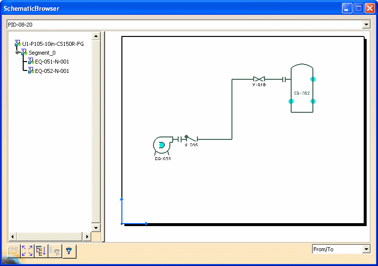
The left side of the Schematic Browser dialog box (the tree section) displays the 2-D/3-D integration status of the listed objects. The integration status updates automatically when the dialog box displays. A green checkmark
A red X
|
|
|
You can manually update the 2-D/3-D
integration status of the objects. However, you must set your Tools
- Options as follows: From the menu bar, select Tools - Options - Equipment and Systems. On the Design Criteria tab, uncheck the Automatic 2D/3D Integration Status Check checkbox. Now when you display the
Schematic Browser,
the integration status does not update, and you see yellow question marks
You also see the Update Integration Status
button
|
|
To update the 2-D/3-D
integration status manually:
|
||
| 2. | In the schematic displayed in the
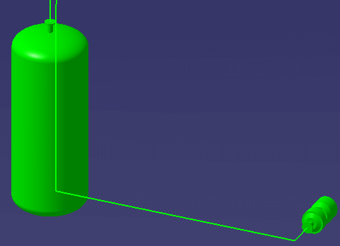
Schematic Browser, click on the run you want to create. The 3-D viewer will
show a possible route.
The function can distinguish the schematic objects (equipment and nozzles only) between which the run existed, and select their 3-D equivalents to route between.
|
|
| 3. | If you want the application to
show you possible paths between two objects, then select your beginning and
end points and click the Display Alternate Path button
|
|
| 4. | Select From/To or Logical Line
|
|
| 5. | Once you have a route you want to
accept, click OK or the Create the Run button
If you named the connectors when you created them (in both the schematic and 3-D applications) then the run will be created between connectors that have the same name as in the schematic. |
|
| 6. | Click the User Defined Path button
|
|
|
|
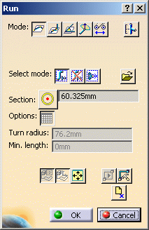
The Run dialog box displays other
options. These are regular Routing options that are explained in Routing a
Run, and allow you to route as you would normally. The Reframe button
|
|
|
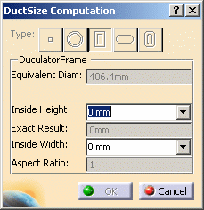
The Ductulator button The Ductulator is a tool for calculating the area of a rectangular or square duct that is equivalent to the diameter of a given round duct. It enables you to place the correct-sized duct. Click the Ductulator button to display the Duct Size Computation dialog box.
The diameter of the line you clicked on is displayed in the Equivalent Diam field. Select a value for the Inside Height property to obtain a value for Inside Width. Or select a value for Inside Width to obtain Inside Height. You should select by clicking on the down arrow next to each field. The values displayed are obtained from your catalog. The Exact Result field displays the exactly computed result. Instead of this figure, the application will select a size that is available to you. The Aspect Ratio field displays the aspect ratio of the two values.
|
||
|
|
||


