| |
The probing process is as follows:

resulting in the following steps:
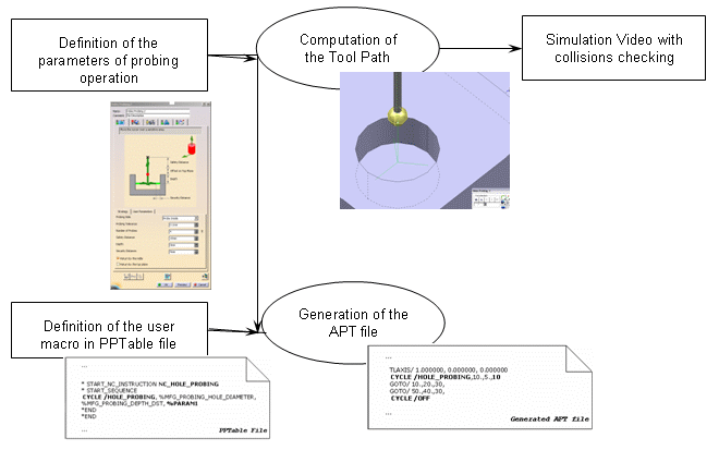
The tool path can be simulated with the video tool to check the collisions
between the tool and the part.
No material is removed and the collision checking is not activated in
probing feedrate.
It is impossible to define exactly all the probing cycles as each
controller has its specific macro for the same cycle.
Therefore, the probing operations can be customized to your needs:
- for the strategy parameters : you can add parameters to the probing
operation, in addition to the standard ones.
- for the format of the output APT file generated : the generated syntax
is configurable in the your PPTable.
Below, you will find the following information:
In the examples below:
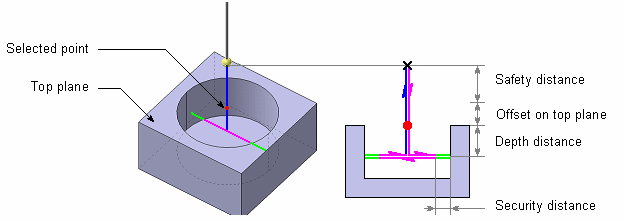
- feedrate for approach is displayed in pink,
- feedrate for probing is displayed in green,
- feedrate for retract is displayed in blue.
Probing Operations:
Geometry and Standard Strategy Parameters
The following probing operations are available:
-
 Holes or Pins Probing: measures the diameter and the center of several holes or pins
-
 Slots or Ribs Probing: measures the width and the middle of a slot or a rib
-
 Corner Probing: measures the internal or external corner
-
 Multi-Points Probing: you define the points to probe and their direction
They share some
standard parameters:
| |
 |
 |
 |
 |
| Probing Side |
Yes |
Yes |
Yes |
|
| Probing Tolerance |
Yes |
Yes |
Yes |
Yes |
| Number of Probes |
Yes |
|
|
|
| Safety Distance |
Yes |
Yes |
|
Yes |
| Distance to probe |
|
|
Yes |
|
| Depth |
Yes |
Yes |
Yes |
|
| Security Distance |
Yes |
Yes |
Yes |
Yes |
| Return by the middle |
Yes |
|
|
|
| Return by the top plane |
Yes |
Yes |
|
|
You can also add your
own parameters.
 Holes or Pins Probing
Output:
The first points of each probing cycle (marked x in the pictures below)
Geometry to select:
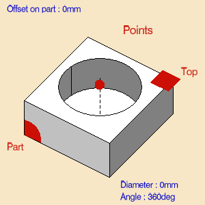
- Probing Side (MFG_PROBING_SIDE):
- Probe Inside to probe a hole,
- or Probe Outside to probe a pin.

- List of geometries composed of points (center of holes or pins to
probe) or guides (contour of holes or pins).
You can select points, circles and cylinders.
- Theoretical Diameter (MFG_PROBING_HOLE_DIAMETER, default value: 0.mm).
If the contour of the hole (or pin) is selected, the diameter is
automatically computed and is associated with the geometry.
Its value is displayed in the sensitive icon. You can:
- remove your selection

and select a new contour,
- Double-click Diameter or Angle and edit it in the dialog box that appears,

- Modify the geometry, hence the diameter or the angle, and retrieve the associativity via the contextual menu:

- Top plane and Offset (MFG_OFFSET_ON_TOP_PLANE, default value: 0.)
Standard strategy parameters:
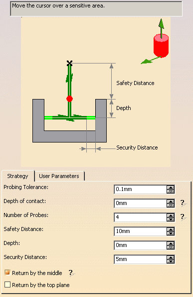
- Tool axis.
The default value is 0., 0., 1.
- Probing direction (MFG_PROBING_DIRECTION_X, MFG_PROBING_DIRECTION_Y,
MFG_PROBING_DIRECTION_Z)
i.e. direction of the first probing.
The default value is 1., 0., 0.
- Probing Tolerance (MFG_PROBING_TOLERANCE): probing
tolerance used in the computation of the tool path,
- Depth of contact (MFG_PROBING_CONTACT_DEPTH): depth of penetration of the
stylus into the material.
- Number of Probes (MFG_PROBING_NB_PROB): Number of probing
points.
The default value is 4, it must be greater than 0.
- Safety Distance (MFG_PROBING_SAFETY_DST).
The default value is 10.mm.
- Depth (MFG_PROBING_DEPTH_DST): Depth Distance.
The default value is 0.mm if you select points.
- Security Distance (MFG_PROBING_SECURITY_DST):
Distance before contact with part to change the feedrate in probing
federate.
The default value is 5.mm.
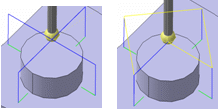
- Return by the middle (MFG_PROBING_RETURN_BY_MIDLE): If this
option is activated, after each probe, the retract goes through the middle
of the hole (or the pin).
Example when the option is activated then deactivated:
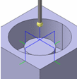
- Return by the top plane (MFG_PROBING_RETURN_BY_TOP_PLANE):
available only to probe holes.
If this option is activated, after each probe, the retract goes through
the top plane.
Examples of:
- PPTable:
*START_NC_INSTRUCTION NC_PROBING_HOLE
*START_SEQUENCE
CYCLE/HOLE_PROBING, %MFG_PROBING_NB_PROB, %MFG_PROBING_HOLE_DIAMETER,
%MFG_PROBING_SAFETY_DST, %MFG_PROBING_DEPTH_DST, %MFG_OFFSET_ON_TOP_PLANE,
%MFG_PROBING_DIRECTION_X, %MFG_PROBING_DIRECTION_Y, %MFG_PROBING_DIRECTION_Z
*END
*END
- Generated APT File: The selected point coordinates are (0.0, 10.0,
0.0).
$$ OPERATION NAME : Hole Probing.1
$$ Start generation of : Hole Probing.1
LOADTL/1,1
TLAXIS/ 0.00, 0.00, 1.00
SPINDL/ 0.00,RPM,CLW
RAPID
GOTO / 0.00, 10.00, 10.00
CYCLE/HOLE_PROBING, 4, 10.00, 10.00, 5.00, 0.00, 1.00, 0.00, 0.00
GOTO / 0.00, 10.00, 20.00
CYCLE/OFF
$$ End of generation of : Hole Probing.1
 Slots or Ribs Probing
Output:
The first points of each probing cycle (marked x in the pictures below).
Geometry to select:
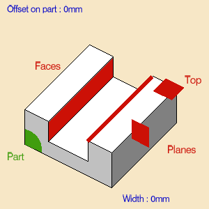
- Probing Side (MFG_PROBING_SIDE).
- Probe Inside to probe a slot,
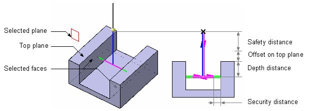
- or Probe Outside to probe a rib.

- Several planes to localize the probe.
- Top plane and Offset (MFG_OFFSET_ON_TOP_PLANE, default value: 0.)
- Two faces or planes which compose the Slot or the Rib.
If the faces of the hole (or pin) is selected the width is automatically
computed and is associated of the geometry.
- Theoretical width (MFG_PROBING_SLOT_WIDTH):
If the faces of the rib (or slot) are selected, the width is automatically
computed and is associated with the geometry.
Its value is displayed in the sensitive icon. You can:
- remove your selection

and select new facesr,
- Double-click Width and edit it in the dialog box that appears,

- Modify the geometry, hence the rib or the slot, and retrieve the
associativity via the contextual menu:

Standard strategy parameters:
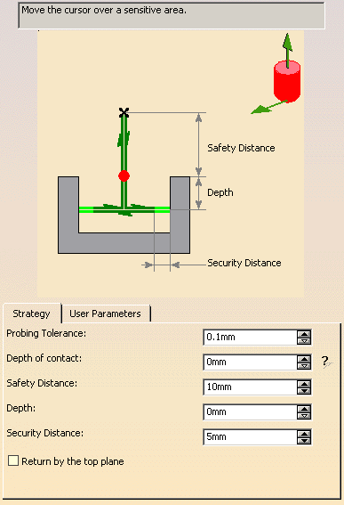
- Tool axis
The default value is: 0., 0., 1.
- Probing direction (MFG_PROBING_DIRECTION_X, MFG_PROBING_DIRECTION_Y,
MFG_PROBING_DIRECTION_Z)
i.e. direction of the first probing.
The default value is 1., 0., 0.
- Probing Tolerance (MFG_PROBING_TOLERANCE): probing
tolerance used in the computation of the tool path,
- Depth of Contact (MFG_PROBING_CONTACT_DEPTH): depth of penetration of the
stylus into the material.
- Safety Distance (MFG_PROBING_SAFETY_DST).
The default value is 10.mm.
- Depth Distance (MFG_PROBING_DEPTH_DST)
The default value is 0.mm.
- Security Distance (MFG_PROBING_SECURITY_DST): Distance before
contact with part to change the feedrate in probing federate.
The default value is 5.mm.
- Return by the top plane (MFG_PROBING_RETURN_BY_TOP_PLANE):
available only to probe holes.
If this option is activated, after each probe, the retract goes through
the top plane.
Examples of:
- PPTable:
*START_NC_INSTRUCTION NC_PROBING_SLOT
*START_SEQUENCE
CYCLE/SLOT_PROBING, %MFG_PROBING_SLOT_WIDTH, %MFG_PROBING_SAFETY_DST,
%MFG_PROBING_DEPTH_DST, %MFG_OFFSET_ON_TOP_PLANE,
%MFG_PROBING_DIRECTION_X, %MFG_PROBING_DIRECTION_Y, %MFG_PROBING_DIRECTION_Z
*END
*END
- Generated APT File:
$$ OPERATION NAME : Slot Probing.1
$$ Start generation of : Slot Probing.1
LOADTL/1,1
TLAXIS/ 0.00, 0.00, 1.00
SPINDL/ 0.00,RPM,CLW
RAPID
GOTO / 0.00, 10.00, 10.00
CYCLE/SLOT_PROBING, 10.00, 10.00, 5.00, 0.00, 1.00, 0.00, 0.00
GOTO / 0.00, 10.00, 20.00
CYCLE/OFF
$$ End of generation of : Slot Probing.1
Output:
The first points of each probing cycle (marked x in the pictures below).
Geometry to select:
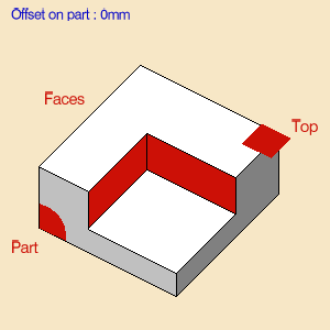
- Probing Side (MFG_PROBING_SIDE).
- Probe Inside to probe a internal corner,
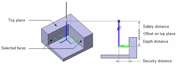
- or Probe Outside to probe an external corner.
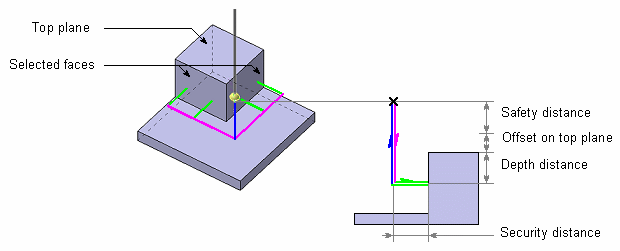
- Top plane and Offset (MFG_OFFSET_ON_TOP_PLANE, default value: 0.),
- Two faces which compose the corner.
Standard strategy parameters:
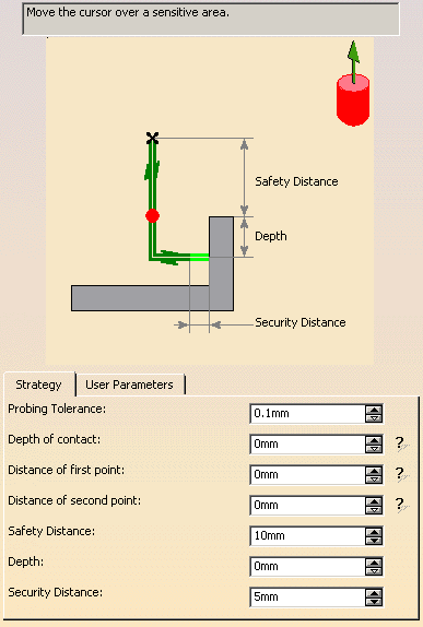
- Tool axis
The default value is: 0., 0., 1.
- Probing Tolerance (MFG_PROBING_TOLERANCE): probing
tolerance used in the computation of the tool path,
- Depth of contact (MFG_PROBING_CONTACT_DEPTH): depth of penetration of the
stylus into the material.
- Distance of first point (MFG_PROBING_FIRST_PROBE):
defines the distance between the corner and the first probing point.
- Distance of second point (MFG_PROBING_DIST_PROBE):
defines the distance between the first and the second probing points.
- Safety Distance (MFG_PROBING_SAFETY_DST).
The default value is 10.mm.
- Depth Distance (MFG_PROBING_DEPTH_DST)
The default value is 0.mm.
- Security Distance (MFG_PROBING_SECURITY_DST):
Distance before contact with part to change the feedrate in probing
federate.
The default value is 5.mm.
Examples of:
- PPTable:
*START_NC_INSTRUCTION NC_PROBING_CORNER
*START_SEQUENCE
CYCLE/INT_CORNER_PROBING, %MFG_PROBING_SAFETY_DST, %MFG_PROBING_DEPTH_DST,
%MFG_OFFSET_ON_TOP_PLANE
*END
*END
- Generated APT File: All macro motions are deactivated.
$$ OPERATION NAME : Int. Corner Probing.1
$$ Start generation of : Int. Corner Probing.1
LOADTL/1,1
TLAXIS/ 0.000000, 0.000000, 1.000000
SPINDL/ 0.0000,RPM,CLW
RAPID
GOTO / 0.00000, 10.00000, 10.00000
CYCLE/INT_CORNER_PROBING, 10.00000, 5.00000, 0.00000
GOTO / 0.00000, 10.00000, 20.00000
CYCLE/OFF
$$ End of generation of : Int. Corner Probing.1
 Multi-Points Probing
Output:
The selected point and its direction, followed by the first point of the
probing cycle (marked x in the pictures below.
Geometry to select:
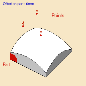
Points to probe and their direction.
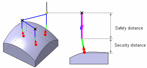 You can: You can:
- select points, in this case their direction is the tool axis.
- pick points on a surface. At each pick, a point is created on the
surface with the coordinates of pointer.
This point is not associated of the face: if the face is modified, the
point will not be modified.
The direction of the point is the normal to the surface.
Standard strategy parameters:
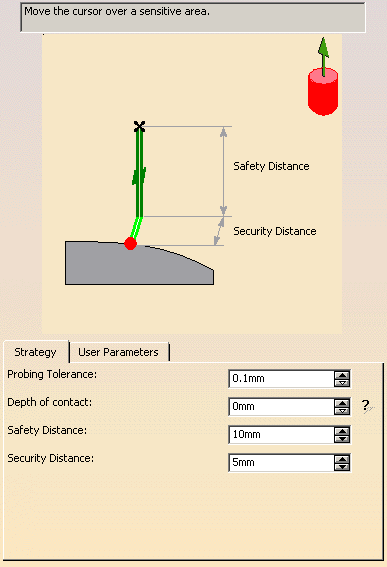
- Tool axis
The default value is: 0., 0., 1.
- Probing Tolerance (MFG_PROBING_TOLERANCE): probing
tolerance used in the computation of the tool path,
- Depth of contact (MFG_PROBING_CONTACT_DEPTH): depth of penetration of the
stylus into the material.
- Safety Distance (MFG_PROBING_SAFETY_DST).
The default value is 10.mm.
- Security Distance (MFG_PROBING_SECURITY_DST):
Distance before contact with part to change the feedrate in probing
federate.
The default value is 5.mm.
Examples of
- PPTable:
*START_NC_INSTRUCTION NC_PROBING_MULTIPOINTS
*START_SEQUENCE
VERIFY/ MULTI_PROBING, %MFG_PROBING_SAFETY_DST
*END
*END
- Generated APT File: All macro motions are deactivated.
$$ OPERATION NAME : Multi Probing.1
$$ Start generation of : Multi Probing.1
LOADTL/1,1
TLAXIS/ 0.000000, 0.000000, 1.000000
SPINDL/ 0.0000,RPM,CLW
RAPID
GOTO / 0.00000, 10.00000, 10.00000
CYCLE/MULTI_PROBING, 10.00000, 5.00000, 0.00000
GOTO / 17.64900, 70.69300, 30.58600, -0.40615, 0.26639, 0.87411
GOTO / 59.80300, 68.11100, 39.42300, 0.07485, 0.26853, 0.96035
GOTO / 20.88300, 27.77500, 31.39400, -0.31938, -0.28117, 0.90496
CYCLE/OFF
$$ End of generation of : Multi Probing.1
This tab page is found in each probing command.
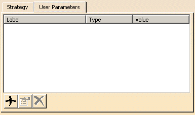
User parameters can be of the following types:
- String,
- Boolean,
- Integer,
- Real,
- Length,
- Angle.
Each user parameters can be generated in the APT file if you modify the
macro of the probing operation in the PPTable.
For example, you add the parameter called "MyParameter" in the hole
probing operation.
Modify the macro NC_PROBING_HOLE by adding "%MyParameter"
to retrieve its value.
 Add: adds an user parameter via this dialog box:
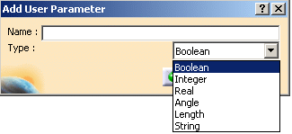
When you click OK, the corresponding edition dialog box is displayed to let
you enter the parameter value.
 Edit: edit the selected user parameter in the corresponding dialog box.
 Remove: deletes the selected parameter.
You can add a comment to User Parameters:
Select a parameter and click Edit
 .
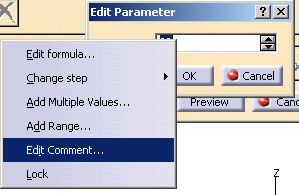
This brings you to the Edit Parameter dialog box. .
This brings you to the Edit Parameter dialog box.
Right-click the value field and select Edit Comment:
This brings you to the URLs & Comment dialog box:
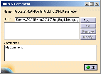
Either type a comment in the dedicated field or click Add to
key-in a URL:
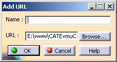
Click OK to validate and exit the dialog boxes.
The content of your comment appears as a tooltip when you place the cursor
over the parameter.
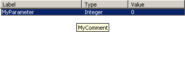
Note that parameters that have no value field require that you use the
formula dialog box.
See the Knowledgeware Infrastructure - Tips and Techniques - Summary
dedicated to the infrastructure knowledgeware capabilities for more
information on formulas.
Case of the Multi-Points Probing
The points selected are displayed under the geometry sensitive icon.
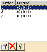
You can:
-
 edit them,
-
 remove them,
-
 reorder them.
Probing Operations: Tools
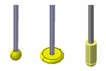
The tools used with the probing operations are ball stylus (or disc stylus:
portion of a sphere) and cylinder stylus:
Probing Operations: Macros
General information about macros can be found in
NC Macros.
Information about the operating mode can be found in
Defining Macros.
Information about Surface Machining macro parameters can be found in
Macro Parameters.
Please note that:
- Approach macro is used to approach the operation start point
(deactivated by default).
- Retract macro is used to retract from the operation end point
(deactivated by default).
- The linking macros can be used to link two probing cycles (deactivated
by default).
- Clearance macro can be used to avoid a fixture or similar (deactivated
by default).
The Clearance macro is only used if the Linking Macros are used.
The macros generated in APT file are managed as the drilling operations.
Examples: Hole probing of 2 holes with the Linking macros deactivated:
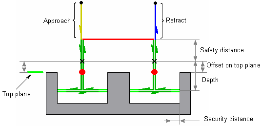
Strategy Parameters:
Diameter = 40mm
Safety Distance = 10mm
Offset on Top Plane = 2mm
Depth = 20mm
Security Distance = 5mm
Macro Parameters:
Approach : Along Tool Axis – 20mm
Linking : Deactived
Retract : Along Tool Axis – 20mm
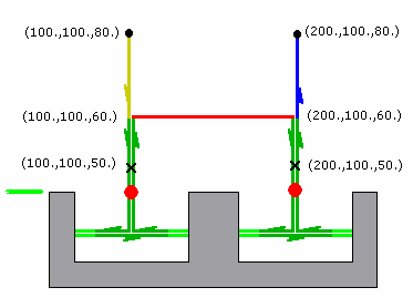
APT Generated:
$$ Start generation of : Holes Probing.1
RAPID
GOTO / 100.0, 100.0, 80.0, 0.0, 0.0, 1.0
FEDRAT/ 300.0000,MMPM
GOTO / 100.0, 100.0, 60.0, 0.0, 0.0, 1.0
CYCLE/PROBING_HOLE, 40.000000, 10.000000, 2.000000, 20.000000, 5.000000
GOTO / 100.0, 100.0, 50.0, 0.0, 0.0, 1.0
GOTO / 200.0, 100.0, 50.0, 0.0, 0.0, 1.0
CYCLE/OFF
FEDRAT/ 1000.0000,MMPM
GOTO / 200.0, 100.0, 80.0, 0.0, 0.0, 1.0
$$ End of generation of : Holes Probing.1
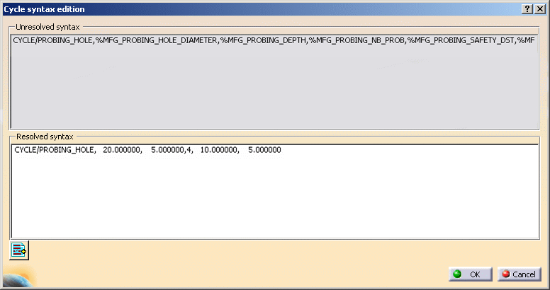
Edit Cycle
 is
available for all probing commands, with the following dialog box: is
available for all probing commands, with the following dialog box:
Add PP word list
 lets you add PP Words.
General information about PP Words can be found in
PP Tables and
PP Word Syntaxes.
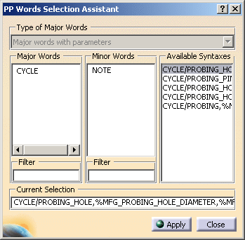
Click here for more
information.
The syntaxes available are:
| Probing operation |
Available syntaxes (where n is a number: 1,2,….)
|
 Holes or Pins Probing Holes or Pins Probing |
NC_PROBING_HOLE
NC_PROBING_PIN
NC_PROBING_HOLE_n
NC_PROBING_PIN_n |
 Slots or Ribs Probing Slots or Ribs Probing |
NC_PROBING_SLOT
NC_PROBING_RIB
NC_PROBING_SLOT_n
NC_PROBING_RIB_n |
 Corner Probing
 |
NC_PROBING_CORNER
NC_PROGING_CORNER_n |
 Multi-Points Probing
 |
NC_PROBING_MULTI_POINTS
NC_PROBING_MULTI_POINTS_n |
|

