![]()
This task shows how to create axis-based joints.
![]()
Open the Ujoint_axis_without_kin.CATProduct document.
Automatic switch to Design mode:
If you work with the cache system in visualization mode, you no longer need to use Edit > Representations > Design Mode beforehand as the switch to design mode is automatic (an eye appears as you point the product in the geometry or specification tree). All you need to do is click on the object.
-
Click Axis-based Joint
 in the
Kinematics Joints toolbar.The Axis-based Joint Creation
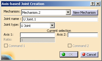
dialog box appears:
-
Specify the joint type using the Joint Type drop-down list:
- u joint
- prismatic
- revolute
- cylindrical
- spherical
In our example we keep the default type: u joint
-
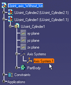
Click the axis1 selection field and select Ujoint_Cylinder1 Axis System.1 either in the geometry or in the specification tree:
-
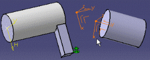
Click the axis2 selection field and select Ujoint_Cylinder2 Axis System.1 either in the geometry or in the specification tree
-
Click Ok to end the u joint creation.
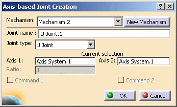
The u joint is created and identified in the specification tree:
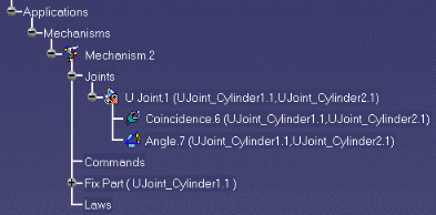
Constraints are created:
-
coincidence constraint between the axis systems origins
-
angle (perpendicular constraint = 90deg) between: x axis from first axis system and z axis from the second axis system
The interest of this creation mode lies in the ability to keep associativity even if you move one part involved in the joint. Before, you could not update the joint.
i.e. If you move a part involved in the u joint, use the update command to make sure the u joint remains associative with the parts involved.
-
-
Open the Ujoint_axis_with_kin.CATProduct document to check your result
![]()
For more detailed information about constraints created using the axis system mode, see More About Resulting Constraints
![]()
Note that it is impossible to create joints using axis from V4 models.
![]()