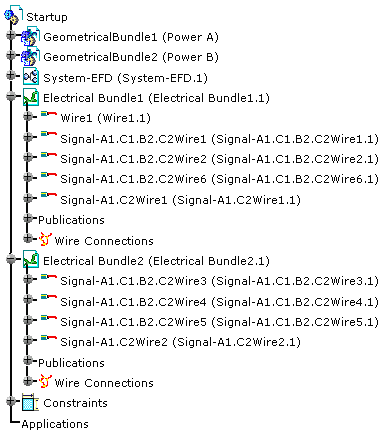
It also explains how the wire extremities are connected according to the signal definition.
How wires are distributed into the bundle segments, how the V5 bundle segment diameter is recomputed and how wires are resolved using an EFD attribute are described in Creating a Wire.
The algorithm optimizes the wire route according to company criteria, with the following capabilities:
- Find the shortest wire route
- Route multiple extremities signals
- Route several signals at a time in compliance with a priority and a rank order
- Manage separation code for compatibility between signal and bundle segment with a compatibility table and CATIA knowledgeware
- Position automatically the connections at the wire forks.
-
Set up the routing context with two signals:
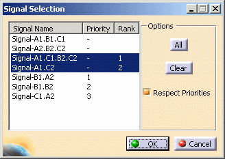
Note that the Rank allows you to choose the selection order during the automatic routing, taking into account possible Priority orders. In our example, Signal-A1.C1.B2.C2 will be routed first, then the other signals according to their ranks. For more information, please refer to Creating Signals in the CATIA - Electrical System Functional Definition User's Guide (step Attributes).
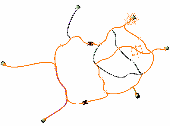
After computation, the result looks like this:
The shortest route has been found and the connections created.
Note: The connection created on Signal-A1.C1.B2.C2 is not displayed in multi-signal mode. Switch to Signal-A1.C1.B2.C2 to view it.
How are Wire Extremities Connected according to the Signal Definition
Wire extremities are automatically connected according to the signal definition:
-
Termination (electrical termination) to termination if terminations exist
-
Connector (electrical connection point) to connector if connectors exist
-
Equipment to equipment if items of equipment exist.
However, when a signal extremity is an item of equipment with mating connectors, the connection is done on the mating connectors:
-
Select the signal in the list box
 ,
for example select Signal-Left.
 -
Click Automatic Wire Routing
 .
.
The wire network is computed. -
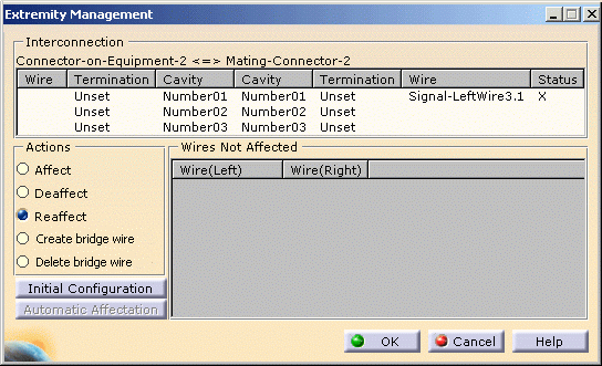
Select a connector, for example, Single-Connector and click Extremity Management
 .
.The Wire1 is connected on the cavity Number03 of the connector Single-Connector referenced in the functional definition (Connector-AX11) 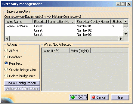
-
Select a connector, for example, Connector-on-Equipment.2 and click Extremity Management
 .
.No wire is connected on this side, but Wire3 is connected on the mating connector belonging to the bundle segment network, on the cavity Number01 corresponding to the functional definition (Mating-Connector.2 corresponding with the functional Connector-AX2) 