It also explains how:
In this section, you will work with bundles created using CATIA V5.
Working with signal routes for space reservation networks created with CATIA - Systems Space Reservation is discussed later.
-
Select the Signal-A1.B1.C1 in the Signal list box.

-
Click New Wire
 .
.
You are prompted to select the segments to map out the wire route. -
Click the following segments:

The Selection dialog box is displayed. As soon as a segment is selected, the window is updated.

-
Enter a name for the wire: Wire1
-
Click OK to validate.
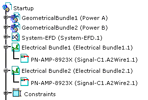
The wire has been created under the electrical bundle and added to the specification tree: 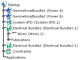
How are Wires Distributed in Bundle Segments?
How is the V5 Bundle Segment Diameter Recomputed?
Consequently the geometry is updated.
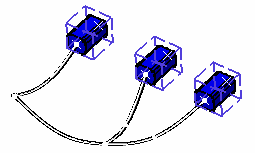
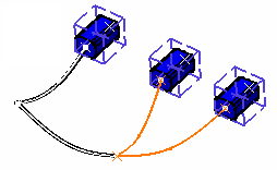
Before: After:
By default, the diameter is computed as follows:
Number of Wires Bundle Segment Diameter N = 0 no change N = 1 wire diameter N = 2 or 3 2 * Max N = 4 and above (1 + 2*((N - 1)/3)1/2) * Max where Max is the largest wire diameter
Automatic Wire Resolution
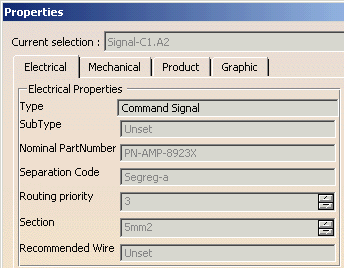
The signal properties dialog box shows the following values: When the wires are created, the specification tree looks like this:
How are Wire Extremities Connected according to the Signal Definition
-
Wires are always created in the correct bundle: using the signal definition to get the functional extremities, then the physical extremities, and the geometrical bundle may be deduced. Since the electrical bundle has been defined through its links to the geometrical bundle(s), it's now possible to create the wires in the correct electrical bundle.
-
Wire extremities are automatically connected to the electrical terminations if it corresponds to the signal extremity.
-
Wire extremities are automatically connected to the wire connection if one exists as an extremity in the signal.
However, when a signal extremity is an item of equipment with mating connectors, the connection is done on the mating connectors. See the example using the automating routing.
