This task shows you how to create user-defined distant connection properties.
- Only available with the Generative Assembly Structural Analysis (GAS) product but some advanced options are only available with the Elfini Structural Analysis (EST) product.
- To have precisions and to know restrictions, refer to About Connection Properties.
Creating user-defined distant connection properties allows
you to specify the types of elements as well as their associated properties
included inside a distant connection.
For example:
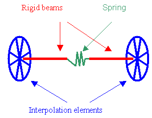
You define which types of element are featured in the connection. Remember that you can possibly have the following types of connected elements:
- Surface-Point part (left part). It describes the way the
surface is connected to the middle of the connection. The possible
combinations are:
- Smooth
- Rigid
- Spring-Smooth
- Spring-Rigid
- Contact-Rigid

- Middle part. It describes the elements featuring in the middle
of the connection. The possible combinations are:
- Rigid
- Spring-Rigid-Spring
- Rigid-Spring-Rigid
- Spring-Rigid
- Rigid-Spring
- Beam
- Spring-Beam-Spring
- Beam-Spring-Beam
- Spring-Beam
- Beam-Spring
- Bolt-Rigid
- Rigid-Bolt
- Bolt-Beam
- Beam-Bolt
- Bolt-Rigid-Spring
- Spring-Rigid-Bolt

- Point-Surface part. It describes the way the surface is
connected to the middle of the connection. The possible combinations are:
- Smooth
- Rigid
- Smooth-Spring
- Rigid-Spring
- Rigid-Contact

Open sample12.CATAnalysis from the samples directory.
-
Make sure you created a Finite Element Model containing a Static Analysis Case from this assembly.
-
Make sure you know all you need about what type of property you will use for what type of connection.
-
Click User-defined Distant Connection Property
 in the Connection Properties toolbar.
The User-defined Connection Property dialog box appears.
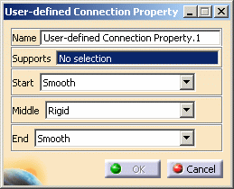
Depending on the selected combination type, the appropriate properties are proposed: lists in sub-windows describing all the elementary properties.
For example:-
If the list of elements is RIGID + SPRING and BEAM + RIGID and CONTACT
-
Three sub-windows (elementary basic components) will display the properties for each of the elements: Spring, Beam and Contact.
-
-
Select an analysis connection as support.
In this particular example, select the General Analysis Connection.1 in the specification tree under the Analysis Connection Manager.1 set.

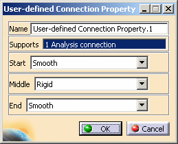
A symbol representing the user-defined connection property is visualized on the corresponding faces.
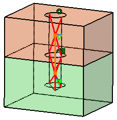
-
Define the types of the elements to be featured in the connection: Start, Middle and End.
Depending on the type of Start, Middle and End elements you choose in the User-defined Connection Property dialog box, given definition boxes and options are available.
This is an example:
Set the parameters as shown below:
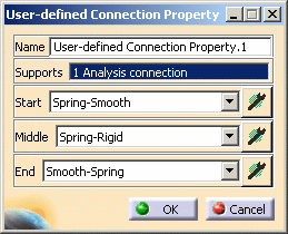
-
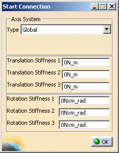
Start: if you click the Component Edition button
 ,
the Start Connection dialog box appears:
-
Axis System Type: lets you to choose between Global or User Axis systems for defining the degrees of freedom directions.
-
Global: if you select the Global Axis system, the degree of freedom directions will be interpreted as relative to the fixed global rectangular coordinate system.
-
User: if you select a User Axis system, the degree of freedom directions will be relative to the specified Axis system. Their interpretation will further depend on your Axis System Type choice.
To select a User Axis system, you must activate an existing Axis by clicking it in the features tree. Its name will then be automatically displayed in the Current Axis field.
If you select the User Axis system, the Local orientation combo box further allows you to choose between Cartesian, Cylindrical and Spherical Local Axis Orientations.
-
-
Translation and Rotation stiffness values.
-
-
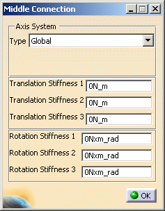
Middle: if you click the Component Edition button
 ,
the Middle Connection dialog box appears:
-
Axis System Type: for more details, refer to the axis system description or refer to Axis System Type.
-
Translation and Rotation stiffness values.
-
-
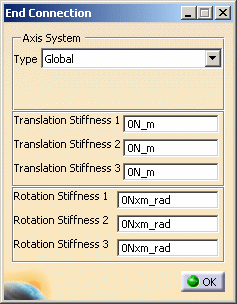
End: if you click the Component Edition button
 ,
the End Connection dialog box appears:
-
Axis System Type: for more details, refer to the axis system description or refer to Axis System Type.
-
Translation and Rotation stiffness values.
-
-
-
If needed, click OK in the Start, Middle or End Connection dialog box.
-
Click OK in the User-defined Connection Property dialog box.
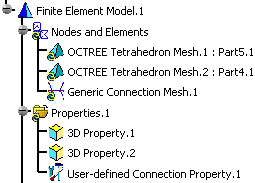
Note that two elements appear in the specification tree:
- A Generic Connection Mesh.1 connection mesh part under the Nodes and Elements set
- A User-defined Connection Property.1 connection property under the Properties.1 set.
- If the support of the connection is a Face to Point connection (connecting wire-frames with solid or surface), only two of the three lists will be proposed (left part and middle part).
- If the support of the connection is a Point to Point connection (connecting two wire-frames), only the middle list will be proposed.
- No handler point is proposed in that type of connection. To ensure that a Face to Face connection will respect a given point, it will be necessary to split into a Face to Point and a Point to Face connection sharing the same point. Like for virtual parts sharing the same handler point, only one single node will be generated on the associated point.
![]()