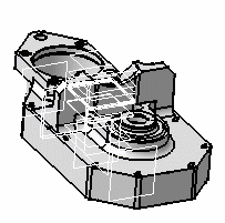
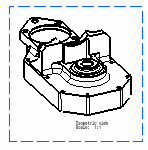
Isometric means "equal measure". To produce an isometric projection, it is necessary to place the object so that its principal edges make equal angles with the plane of projection and are therefore foreshortened equally. Note that an isometric view created from a product can be re-used for generating an exploded view.
-
In the Drawing window, click Isometric View
 in the Views toolbar (Projections sub-toolbar).
-
Define the 3D viewer orientation according to the result you want to obtain in the view. To do this, you can either manipulate the viewer directly, or use the View > Named Views command in 3D to define your orientation precisely.

Prior to defining your orientation, it may be useful to use different canonical points of view by defining the corresponding local axis systems in 3D. For more information, refer to Axis System in the Part Design User's Guide. 
-
Click the 3D part.
A green frame with the preview of the isometric view to be created, as well as blue arrows, appear. You can re-define the reference plane orientation of the view to be created using these arrows: to the bottom, the left, the right, the top, or rotated using a given snapping or according to an edited rotation angle. For more information, refer to Before You Begin > Defining the view orientation.
-
Click on the sheet to generate the view.

- You can use selection sets to generate isometric views displaying a selection of elements only. Selection sets let you select the sub-bodies and/or sub-products from which the view will be generated. Refer to Creating a front view using selection sets for more information.
- In a Product Structure context, if you create a front view from a scene of a product, you can directly select the Scene object in the specification tree. You do not necessarily need to select the Product and sub-products.
![]()