- Understanding the 3D Cut Capability
- Alternate Shape Management
- Step-by-step Scenario
- Limitations
- Results - Examples
Understanding the 3D Cut Capability
3D Cut functionality cuts through a model computing the intersection (or the difference as defined by the user) between a CATPart, a CATProduct, a multi-selection of CATParts and a 3D box. The result is a truncated polygonal mesh, lighter than the original selection which can be saved as an independent geometry.
Note that the resulting geometry keeps color attributes as well as faces and edges. The resulting 3D Cut can be automatically treated as an alternate shape as in any other DMU Optimizer functionality.
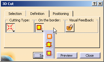
By default, the On the Border
behavior is set to
![]() (allows you to cut the triangles on the selection border within the
cutting box). The result is a boolean intersection between the
selected model and the section box; the triangles are cut.
(allows you to cut the triangles on the selection border within the
cutting box). The result is a boolean intersection between the
selected model and the section box; the triangles are cut.
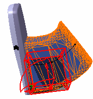
Initial model |
Intersection treated as: |
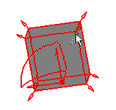
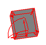
Section Box |
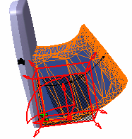
Result |
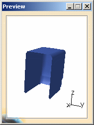
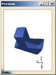
3D Cut Preview |
| Volume | Volume |
 |
Closed volume |
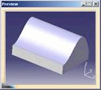 |
| Surface | Open Surface |
 |
Surfaces that are coincident with the section box are removed. |
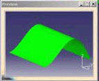 |
 |
If you want to keep the surfaces, extend the section box. |
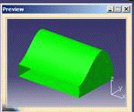 |
![]()
Step-by-Step Scenario
This task will show you how to create 3D cut
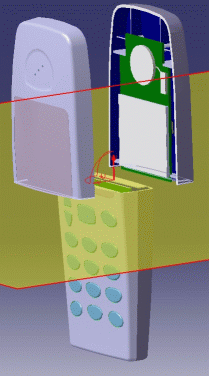
Open Mobile_Phone.CATProduct document.Use Fit All In
![]() to position the model geometry on the screen.
to position the model geometry on the screen.
Alternate Shape Management
-
(Optional)
You can manage automatically your result as alternate shape of the initial component. For this:- Select Tools > Options from the menu bar.
The Options dialog box is displayed. - Expand the Digital Mockup category from the left-hand tree.
- Select DMU Optimizer item to display the corresponding tab. The Alternate Shapes Management is available
- Select the 3D Cut option: it is automatically activated as an alternate shape. When activated the 3D cut representation is the one visualized in session.

- Select Tools > Options from the menu bar.
-
Right-click Battery(Battery.1) in the specification tree and select Representations > Manage Representations... from the contextual menu displayed
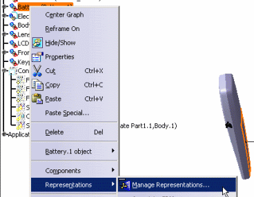
The Manage representations dialog box is displayed -
Select Battery.1_SWEPTVOLUME.cgr and click Activate button in the Manage Representations dialog box displayed.
-
Click Close
-
Click 3D Cut
 in the
DMU Optimizer
toolbar.
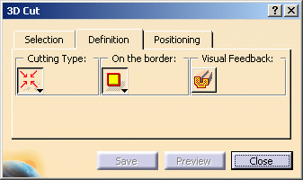
The 3D Cut dialog box is displayed: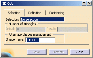
This dialog box contains a variety of tools letting you positioning the section box and selecting the cutting type -
Select Battery.1 either in the specification tree or the geometry area
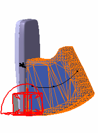
Product (s) selected are highlighted in the specification tree and geometry area The section box is not yet correctly positioned (not snapped onto the battery) 
Note: if you select the product(s) of interest for your selection before entering the 3D Cut command, the section box will be automatically positioned on the selected product(s). -
Click the Positioning tab and click the Reset Position icon

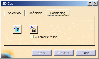
The section box is positioned with respect to the selection: 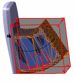
-
Select the automatic Reset check box.

This new capability lets you reset the section box on a selected product with correct dimensions. For example, if you change your selection:
- select Front shell either in the geometry area or in the specification tree, this is what you obtain:
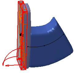
- select again Battery.1, the section box is positioned and resized accordingly
see picture in step 7 -
Adjust the thickness of the section box:
-
Clicking the Edit Position and Dimensions icon
 and entering
the desired values in the Edit Position and Dimensions
dialog box displayed:
 - For more information about the Edit Position and Dimensions dialog box, read refer to Sectioning section in DMU Space Analysis User's Guide
- Units are current units set using Tools > Options (Units tab under General > Parameters and Measure).
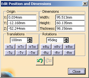
Notes: The Undo and Redo icons in the Edit Position and Dimensions dialog box let you cancel the last action or recover the last action undone respectively.
Only the section box position is recovered, the dimensions are not. -
-
positioning the cursor over one of the slave box plane edges, clicking then dragging to translate the plane in the desired direction
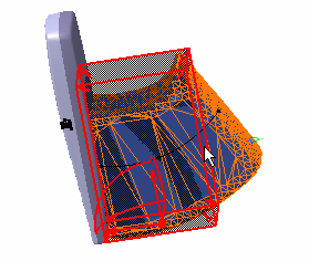
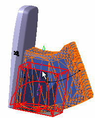
- As you move the cursor over box edges, the cursor changes appearance and arrows identifying the directions along which box thickness is defined appear.
- You can also re-size the box by clicking and dragging one of the box sides. Arrows likewise appear to help you.
-
Click the Definition tab to select the desired cutting types.
-
Still in the Definition tab page, click Volume Cut
 in the Visual Feedback area to obtain a section cut.
This capability gives you an automatic visual feedback of what you can get, for instance if you resized the section box as following: 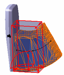
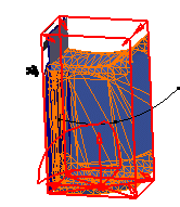
The material is cut away exposing the cavity of the product. Click Volume Cut  again
to go back to the initial state.
Note: the volume cut is purely visual and therefore cannot take into account the cutting type (in/out) -
Click Preview when satisfied
-
Click Save. The Save As dialog box automatically appears:
- Set the Type to .cgr. You can also save your resulting shape in .wrl, .model .stl formats
- Identify the folder in which you want to save the file
- Enter a file name
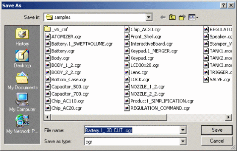

Note: clicking Save keeps the command active and lets you therefore launch the calculation again if needed. When satisfied click Save in the Save As dialog box. Click Close to exit the dialog box. -
Click Close
-
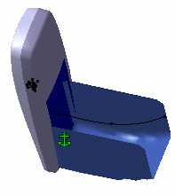
In our scenario, we managed the result as an alternate shape, therefore the 3d cut replaces the original representation:
|
|
Notes:
|
Limitations
If a surface body intersects the border of the 3D box, then its edges are lost. Edges are kept only for surface bodies entirely inside or outside the 3D box.
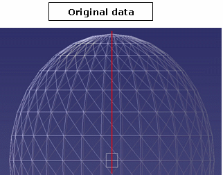
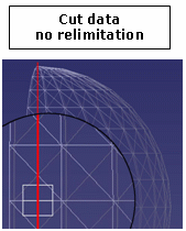
When the Cuts the triangles option is not selected
The 3D Cut functionality does not relimit the triangles of the initial mesh
intersecting the boundaries of the 3D box.
Result: triangles are integrated entirely (or rejected entirely, as
defined by the user.)
Note that triangles whose vertices are outside the 3D box are considered totally outside.
 |
 |
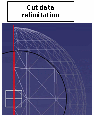 |
When the Cuts the triangles option is selected
Note that the computation time is increased (it can be increased up to two times that of the previously measured computation time)
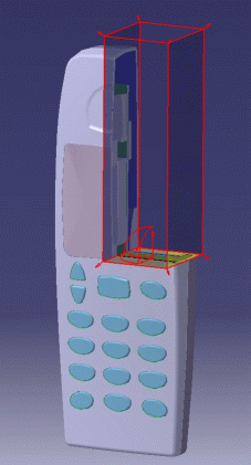
Results - Examples
 |
 |
![]()
