-
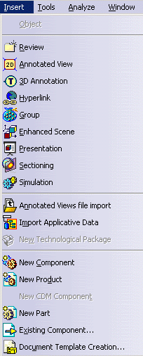
Select the Insert -> Existing Component... command.
It is possible to insert a component via HTTP in visualization mode. The document will be visualized and a cgr file will be generated in the cache. Supported document types are:
- CATPart
- model
- cgr
![]()
-
In the Insert an Existing Component dialog box, select the file location.
-
Click the Files of type: list.
-
Select the desired type from the following:
Formats supported on all operating systems:
- CATIA V4 Assembly Modeling Files (*.asm) (In CATIA Only)
- BYU
- CATIA V5 Parts (*.CATPart)
- CATIA V5 Products (*.CATProduct)
- CATIA Graphical Representation Files (*.cgr)
- DenebDevice (*.dev)
- CV Graphic ASCII Format (*.gaf)
- CV Graphic Binary Format (*.gbf)
- Ideas Facetted Format (*.iff)
- CATIA V4 models (*.model)
- CATIA V4 session (*.session)
- NCGM (*.ncgm)
- WaveFront OBJ (*.obj)
- PDB files (*.pdb)
- PS Optegra files (*._ps)
- SLP (*.slp)
- STL (ASCII and binary) (*.stl)
- Deneb Workcell (*.wcl)
- VRML 2.0 Files (*.wrl)
- iges
- STRIM and STYLER models (*.tdg)
- N4D Scenes (*.wrl) (geometry and product references only)
- HSF version 14.0 (*.hsf)
Note: For Pro/Engineer, Ideas and Unigraphics Multi-CAD file types that can be inserted into DMU Navigator documents, see the corresponding documentation:
- MULTICAx PD Plug-in (Pro/Engineer)
- MULTICAx ID Plug-in (Ideas)
- MULTICAx UD Plug-in (Unigraphics)
- 3D XML
The following applicative data can now be saved in 3D XML format:
- Annotated View
- Alternate View (Enhanced Scene)
- Presentation
- Section
- Measure
- Animation
For more information concerning the 3D XML format, see the following tasks in the Infrastructure Guide:
Formats supported on Windows only:
- dxf3D Parts (*.dxf)
- SolidEdge Parts (*.par)
- Acis (SAT) (*.sat)
- SolidWorks Assemblies (*.sldasm)
- SolidWorks Assemblies (*.SLDASM)
- SolidWorks Parts (*.sldprt)
- SolidWorks Parts (*.SLDPRT)
- ParaSolidX_B Parts (*.x_b)
- ParaSolidX_T Parts (*.x_t)
![]()
- A Loading in Progress dialog box indicates how many objects remain to be visualized.
- You can interrupt this loading process by clicking the
Interrupt
button.
![]()
- SLP
- STL
- OBJ
- BYU
- IFF
- _PS
Note: For a file of type _PS, the Visu Format Unit must be set to 10.
-
Click Open in the dialog box.
The DMU Navigator document now looks like this:

You need to check the option Do not activate default shapes on open. For more information, see Product Structure in the Infrastructure User's guide.
![]()
Using File ->Open, you can open 2D documents in the following formats:
- cgm
- V4 model (in ENOVIA-DMU Navigator only the draft tab is available)
- AutoCAD files (*.dxf, *.dwg)
- CATIA V4 drawings (*.model)
- CATIA V4 image files (*.picture)
- CATIA V5 CATDrawing (*.CATDrawing)
- tiff, jpeg, bmp, picture (and other 2D Raster formats)
- HPGL
- HPGL2 (supports images and is printable)
- text support
- color and line types attributes
- polyline support
- dimension support
Note: Some limitations remain in the current version:
- strikethrough and underlined text attributes are not taken into account
- polylines are not filled
- hatching is not supported
- vertex entities are not correctly transcribed
- viewport is not supported
Inserting Sample Documents
Sample documents installed along with the online help library are provided in many cases to support the scenario that explains how a specific command works.
In the online documentation filetree, there is one samples folder for each user's guide. For more information on where sample documents are installed by default, see Accessing Sample Documents in the Infrastructure User's Guide.
