- Joint jogging, which can be performed on devices with forward kinematics defined (inverse kinematics are not required).
- Cartesian jogging, which works only for kinematics devices supporting inverse and forward kinematics (e.g., robots)
- Moving to the home position (the home position(s) is defined in the .CATProduct data used to create the device data).
A kinematics device can be loaded from either a legacy DELMIA device file or a DMU kinematics model, or the device can be created with the V5 Device Building product.
-
Click Device Move
 from the Simulation Activity Creation toolbar.
 The Activity Creation Options dialog box appears. 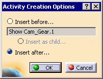
-
Select the location for the activity and click OK.
-
On the PPR tree, select the device you want to move.
The Jog dialog box appears. 
The Jog dialog box enables you to see the effects of the device move in one of two ways: - If the Immediate option is selected, any alterations to the dialog box immediately appear on the geometry.
- If the Immediate option is not selected, you can select the Apply Position button to make the effects of the movements appear on the geometry.
At any time prior to selecting the Close button, you can return the the geometry to its original position by pressing the Reset button. You can create multiple device move activities while the dialog box is open by pressing the Create Activity button. You might need to press the Apply Position button to see the change if the Immediate option is not selected. Pressing the Close button removes the dialog box from the screen; it does not create an activity. To set unique motion attributes for any device move activity, you can select the Set Motion Attribute option. 
For information about motion attributes, see About Motion Attributes. -
Use the dialog box to create one or all of the device move activities listed above:
- To create a joint jogging activity, go to Move (Jog) Joints Activity.
- To create a move home activity, go to Move Home Activity.
- To create a Cartesian jogging activity, go to Move Cartesian Activity.
Move (Jog) Joints Activity
-
Select the joint jogging tab (in the image, IRBL6_2.1) if it is not already on top.
By default, the Jog dialog box opens with the joint jogging tab on top, and the title of the joint jogging tab is the name of the device. The number and kind of degrees of freedom (DOF) displayed in the dialog depends on the device selected. The joint values are displayed graphically as bars. The limits are also displayed on these graphical bars (e.g., -170 to 170 in Joint 1, above). When a joint value exceeds a limit, the bar becomes red and text in the bar shows by how much the limit has been exceeded. By default, prismatic joints show DOFs in mm; rotational joints show them in degrees. To alter the default, see Tools > Options > General > Parameters > Units. The Linear Step box controls the increments by which prismatic joints' values can change; the Angular Step box controls the increments by which rotational joints' values change. -
Manipulate the device using one of the methods described below:
-
On the dialog box, manipulate the lever on the individual degrees of freedom (DOF) scale.
-
On the dialog box, alter the numerical DOF values.
-
On the 3D inventory window, you can move each joint using the manipulator arrow associated with the device (see curved arrow below).
-
-
Once the movement (and, optionally, any motion attributes) is set as desired, click the Create Activity button.
A MoveJointActivity appears on the PPR tree. -
Do one of the following:
- To create another joint move activity for this device, return to Move (Jog) Joint Activity.
- To create a move home activity for this device, go to Move Home Activity.
- To create a Cartesian move activity for this device, go to Move Cartesian Activity.
- To cease creating device move activities for this device, press the Close button (procedure finished).
Move Home Activity
-
Select the joint jogging tab, if it is not already on top.
By default, the Jog dialog box opens with the joint jogging tab on top, and the title of the tab is the name of the device. -
From the Home Position list, select a predefined home position
-
Press the Create Activity button.
A MoveHomeActivity appears on the PPR tree. -
Do one of the following:
- To create another joint move activity for this device, return to Move (Jog) Joint Activity.
- To create a move home activity for this device, go to Move Home Activity.
- To create a Cartesian move activity for this device, go to Move Cartesian Activity.
- To cease creating device move activities for this device, press the Close button (procedure finished).
|
|
In the example below, only one home position is available. However, depending on how the .CATProduct data for the device has been created, more than one home position may be available. |
 |
Move Cartesian Activity
-
Select the Cartesian tab if it is not already on top.
The options on the dialog box are explained in the following table: TCP Controls
Coordinates
X, Y, Z Y, P, R
(Yaw, Pitch, Roll)When you alter the coordinates of the TCP Controls, you move the device. The Tool Center Point (TCP) is defined as a profile in the controller. w.r.t Current Frame Object/ w.r.t Base The coordinates can be named with respect to (w.r.t.) the Current Object Frame or Base. Steps
Linear Step This box controls the increments by which the x, y, and z coordinates can change. Angular Step This box controls the increments by which the yaw, pitch, and roll values change. Snap Compass
Control Location If compass location is checked, the TCP location matches the compass location. Control Orientation If compass orientation is checked, the TCP orientation matches the compass orientation. When the user switches: - from ON to OFF, neither the TCP nor the compass get modified
- from OFF to ON, the compass jumps to the TCP location or orientation.
TCP
Orientation - World
- The compass at the current TCP position keeps its orientation as world. The user can drag the compass along the world's x, y, z direction. Rotation around the world's x, y, z direction is possible. Each time after drag, the compass restores its orientation (which is still the world's orientation).
- Base
- The orientation is the robot's base orientation.
- User
- A define plane toolbar appears, which allows the user to define any orientation by several methods: geometry plane, edge, 3 points, circle center etc.
- Once selection is done, the compass jumps to that point. Any translation or rotation occurs in respect to that point. The compass jumps back after each drag. This serves as a kind of temporary TCP, and no tool profile stores its position.
- Tool
- Once Tool is selected, the Definition box becomes available. The user can select any existing tool profile from the Definition list.
Definition When a tool profile is selected, the compass will jump to its defined TCP position. It becomes temporarily current. If this is done in the context of teach, any new operation created stores this profile in the motion activity. If any Orientation other than Tool is selected, this field is not available.
Configurations and Turn Numbers
Configurations The configurations and turn values, which define the posture of the robot, are set in the .CATProduct file containing the robot data. These configurations are an attribute of the device, and cannot be altered. You can select different, reachable configurations. Turn number Applicative Frame
Set Motion Attributes To set motion attributes, select the Set Motion Attributes check box. For information about motion attributes and the Motion Attribute dialog box, see About Motion Attributes. Create Activity To create a Move Cartesian Activity, you must select the Create Activity button. If you do not select the button, you may see the device in a position other than the one in it was in when the Jog dialog box was opened, but no activity will have been created to record the movement for a simulation. Immediate If Immediate is not checked, then you cannot see the device movement when you alter the TCP or configuration values. Click the Apply Position button to see the position. -
Manipulate the device using one of the methods described below:
- On the dialog box, you can change the values listed on the
TCP Controls.
You can choose whether the coordinate values are set relative to the base or to the world (the default is relative to the world). - On the dialog box, you can select a new configuration.
- On the 3D inventory window, you can manipulate the compass attached to the device (see the table for information regarding the effects of Snap Compass options).
- On the dialog box, you can change the values listed on the
TCP Controls.
-
Once the movement (and, optionally, any motion attributes) is set as desired, click the Create Activity button.
A MoveCartesianActivity appears on the PPR tree. -
Do one of the following:
- To create another joint move activity for this device, return to Move (Jog) Joint Activity.
- To create a move home activity for this device, go to Move Home Activity.
- To create a Cartesian move activity for this device, go to Move Cartesian Activity.
- To cease creating device move activities for this device, press the Close button (procedure finished).