-
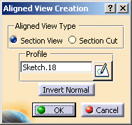
Click the Aligned Section View/Section Cut
 . The
Aligned
View Creation dialog box is displayed.
 -
Specify the type of view that you want to create: Section View or Section Cut. For the purpose of this scenario, select Section View.
-
Click the Sketch
 to sketch a new profile that
will be used as cutting plane.
Note that, at this stage, you can also select an existing sketch, if one is available; in this case, you can only select a sketch which is valid for the type of view to be created. For more information on using this method, you can refer to Creating an Offset Section View/Section Cut: the procedure is similar when creating aligned section views/section cuts.
-
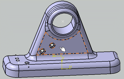
Select a planar surface.
The application switches to the Sketcher workbench to let you sketch the cutting profile.
-
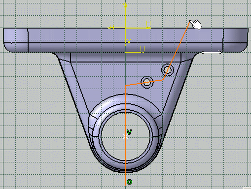
Click the Profile icon:

-
Sketch your cutting profile as shown here.
You can constrain the sketch lines in order to ensure their position according to some features of the part.
-
When you are done, click Exit workbench
 to exit the Sketcher workbench. The newly created sketch, Sketch.18, is
now selected in the Profile field of the Aligned
View Creation dialog box.
Clicking the Invert Normal button lets you invert the normal of the aligned section view: this actually inverts the normal of the section views/annotation planes that make up the aligned section view.
-
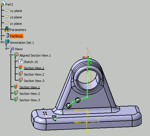
Click OK. The aligned section view is now created and listed in the specification tree; it cannot be activated. It is made up of three distinct section views/annotation planes, each of which can be activated and behaves like a regular section view/annotation plane. Each view is associative to the sketched line that defines it.
You can now start creating annotations in each section view of the aligned section view. If you then extract the aligned section view to 2D in the Generative Drafting workbench, all the annotations defined in each component view will be generated.
-
Optionally, right-click Aligned Section View.1 in the specification tree and select Invert Normal in the contextual menu if you want to invert the normal of the aligned section view: this actually inverts the normal of all the section views/annotation planes that make up the aligned section view.
- The Invert Normal contextual command is only available if there is no annotation attached to any component view of the aligned section view/section cut.
- You cannot perform the following operations for the component sections views/section cuts of an aligned section view/section cut: Delete, Invert Normal and Change View Support.


