- work on the evolution of an assembly in a separate window from the actual assembly and to impart updates to the assembly as you see fit.
- save a copy of an assembly in a separate window, work on the evolution of that assembly directly on the assembly, and to revert to the saved copy if you are not satisfied with the modifications (in this usage, modifications can be replicated in the assembly using the command Applying a Scene in an Assembly.
You can modify the following attributes either in the scene or in the assembly without the modifications being replicated in the other:
- the viewpoint
- the graphical attributes of the components
- the "show" or "hide" state of the components
- the "active" or "not-active" state of the components
The modification of component position is treated as follows:
- modification of component position in the assembly is replicated in the scene as long as the components are synchronized for this scene.
- modification of component position in the scene is not replicated in the assembly and also has the effect of de-synchronizing all components having the same parent as the moved product.
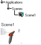
Scenes are identified by name in the specification tree and by a graphical representation in the geometry area.
When you create a scene, the data that will constitute the scene is a function of the current selection in the specification tree. There are three different possibilities:
- if no element is selected in the specification tree or if the selected object in the specification tree is the root product, then the newly created scene will include the data of the entire assembly.
- if a sub-product of the assembly is selected in the specification tree, then the newly created scene will include only the data of that sub-product.
- if an existing scene is selected in the specification tree, then the newly created scene will be a copy of that scene.
The following operations are not allowed in scene context:
- add
- remove
- replace
- cut
- delete
- paste
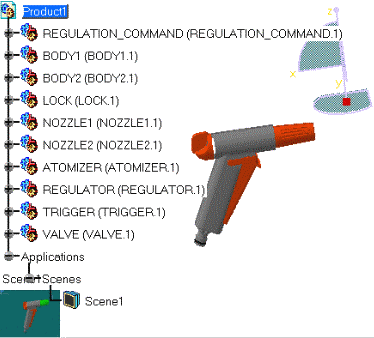
- ATOMIZER
- BODY1
- BODY2
- LOCK
- NOZZLE1
- NOZZLE2
- REGULATOR
- TRIGGER
- VALVE
- REGULATION_COMMAND
-
Click Create Scene
 .
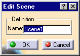
The Edit Scene dialog box and a scene representation in the document window
are displayed.


-
Click Ok to end the scene creation. You are now in a scene window. The background color turns to green. Scene 1 is identified in the specification tree.
-
Perform the required modifications. For instance modify:
- viewpoint
- graphical attributes
- show-no show
Within a scene, click Reset selected products to reposition the components as they were in the initial product. Note that
color attributes and the show-hide specification are not taken into account
when using Reset selected
products.
 -
Click Exit From Scene
 to swap to the initial window.
The scene is updated to reflect any changes made.

-
Double-click Scene 1 in either the specification tree or the geometry area to swap to the scene window.
-
Create as many scenes as needed.
Deactivating View > Scene Specification Visible in the menu bar removes the scene representation and lets you use the entire screen for the product. You can also use the F4 key to toggle more quickly.