 |
-
Click
Select
 to enter selection mode, if it is not already activated.
-
Point to the part of the object you want to select.
| As you point to objects, different
parts of the objects are highlighted, in the geometry area, and the
object name is highlighted in the specification tree: |
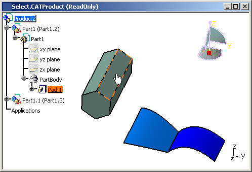 |
| The identity of the preselected element
is displayed in the status bar: |
 |
|
Highlighting is
active only if you selected Preselect in geometry view
(active by default) in Tools > Options > General > Display >
Navigation. You can also set the preselected element linetype
using the Preselected element linetype check box. The
face on the object opposite, for example, is highlighted in red.
|
| You can also use the same tab to set a
variety of useful selection features including selected element
color and pre-selected (highlight) linetype. Note that the
selection color and pre-selection color are the same. |
In the geometry area, you can select the
constituent elements of objects, in other words:
- faces
- vertices
- edges
- planes
- axes.
|
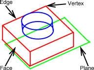 |
| Whenever you are using an application
command, you can only select objects required as input for the
command. For example, when creating a hole in a pad, you are
prompted to select a face or a plane: no other elements can be
selected. |
-
Once the element is highlighted, click on the object to
select it:
-
Hold down Ctrl and select another face to add
it to the initial selection:
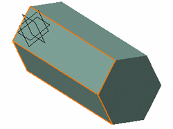 |
 |
Holding down Ctrl
+ selecting can be done in:
- the geometry area
- the specification tree
- lists in dialog boxes.
Holding down Shift + selecting can be done in:
- the specification tree
- lists in dialog boxes.
|
-
To deselect, click anywhere in the background.
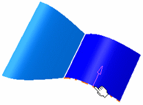
Edges are highlighted as
you point them and arrows are displayed to indicate to which
element the edge belongs to.
This is especially useful in case of overlapped elements as shown
in our example: |
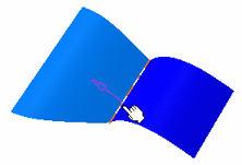 |
 |
|
Pressing Esc
deselects all selected elements. |
|
|
![]()
 to enter selection mode, if it is not already activated.


![]()


