 |
The Parallel contour mode proposes a contextual menu to
define the Guide:
The contents of the contextual menu and of the sensitive icon change
depending on which item have been selected previously.
By default, you are in Guide contour mode, i.e. in a standard geometry
selection mode. |
 |
Open file FreeFormShape1.CATPart,
then select Machining > Surface Machining in the Start
menu. |
 |
-
Click Contour-driven
 . .
The Contour-driven dialog box is displayed.
The dialog box opens at the geometry tab page
 . .
Click the red area in the sensitive icon and
select the whole part.
-
Go to the Strategy tab. Click Parallel
contour.
-
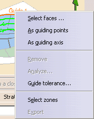
Right-click Guide 1 in the sensitive icon and choose
Select faces...
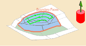
The sensitive icon turns to:
-
Click Boundary Faces in the sensitive icon and
select faces as shown below.
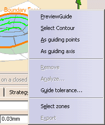
Click Preview Guide in the Boundary Face contextual
menu to visualize the contour.
|
 |
-
The faces you select must be topologically clean.
-
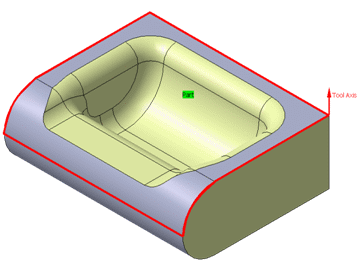
In the case of an open face, the guide is computed from the external
boundary.
Here are two other examples of computed guide (shown in red):
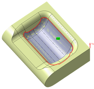
|
|
|
-
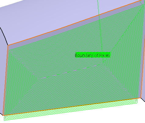
In the Radial tab, select the Reference:

either Contact point:
or Tool end:
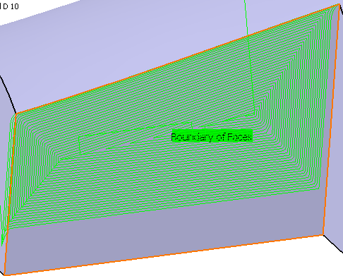
-
Click Tool Path Replay.
The tool path is
displayed.
Click OK to validate and exit the dialog box.
-
Click Contour-driven
 . .
The Contour-driven dialog box is displayed.
The dialog box opens at the geometry tab page
 . .
Click the red area in the sensitive icon and
select the whole part.
-
Go to the Strategy tab. Click Parallel
contour.
-
Right-click Guide 1 in the sensitive icon and choose
As guiding points

The sensitive icon turns to:
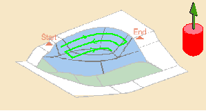
-
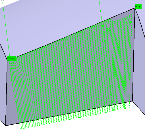
Click Start and select a point in the 3D
Viewer.
Click End and select a point in the 3D Viewer.
(after each selection, double-click anywhere to revert to the dialog box.)
-
Click Tool Path Replay.
The tool path is
displayed.
Click OK to validate and exit the dialog box.
-
Click Contour-driven
 . .
The Contour-driven dialog box is displayed.
The dialog box opens at the geometry tab page
 . .
Click the red area in the sensitive icon and
select the whole part.
-
Go to the Strategy tab. Click Parallel
contour.
-
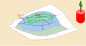
Right-click Guide 1 in the sensitive icon and choose
As guiding axis

The sensitive icon turns to:
-
Click Start and select a point in the 3D
Viewer.
Double-click anywhere to revert to the dialog box.
-
Click Axis and define an axis in the dialog box
that is displayed:
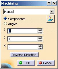
Click OK to revert to the main dialog box.
The direction is displayed through a red arrow while the dialog box is
open,
through a black one after you have closed the dialog box.
-
If necessary increase the
Maximum width to machine.
-
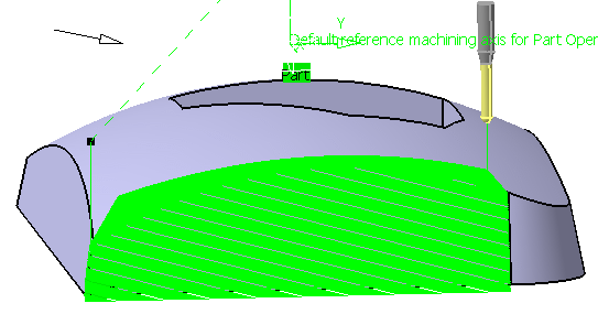
Click Tool Path Replay.
The tool path is
displayed.
Click OK to validate and exit the dialog box.
|
|
 |