 |
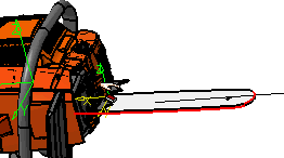
This task describes how to create a track generated along one or more edges.
You can use one or more edges. The edges do not have to be continuous, although
if the edges are discontinuous, the track that results will have a large
jump within it. Once Generate Track  has created the
track, the Manipulation, Player, and Recorder
toolbars appear, which enable users to modify the track. has created the
track, the Manipulation, Player, and Recorder
toolbars appear, which enable users to modify the track. |
 |
-
Click Generate Track
 . .
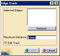
| The Edge Track dialog box appears. |
 |
-
On the geometry, select the edge or edges that you want
to use to define the track.
| The edges appear in the Selected Edges box.
The order the edges are selected is the order they are used to
generate the track. Before you create the track, you can remove
an edge from the list by selecting it in the Selected Edges
box, and clicking the Remove button.
As you select an edge, it becomes highlighted on the
geometry. |
 |
-
Enter a distance for each shot and click OK.
| Generate track creates a shot at the beginning of each edge
and at the end, in addition to the intervals in between.
For instance. if the edge is 3.75 mm, and the Distance
is set to .5 mm, then the distance between the last two shots is
.25 mm, although others are spaced .5 mm apart. |
| If the Edit Track check box is selected (the
default), clicking OK generates the track and also
brings up the Edit Track dialog box, and the
Recorder, Manipulation, and Player
toolbars. Also, a track is generated before the
Edit Track dialog box appears, so if you click
Cancel on the Edit Track dialog box, the track
is nonetheless created. |
-
Edit the track as desired, and click OK in the Edit
Track dialog box.
|
 |
Once you have created a track using Generate Track  ,
you can associate items with it or modify
it as you do other tracks. ,
you can associate items with it or modify
it as you do other tracks. |
|
|
Objects on which You Can Select Edges
|
|
|
For Generate Track  to work properly, it must contain selectable edges. Certain edges, such
as those from CGR data, may not be selectable. To enable CGR data to
have selectable edges, save it with lineic elements, using
the Tools > Options > Infrastructure > Product Structure > Cgr
Management tab. The tables that follow describe the objects
whose edges are selectable.
 |
|
|
V5 Data
|
|
|
| |
Load as CATPart |
Saved as CGR |
| V5 Data |
Cache Off |
Cache On |
Cache Off |
Cache On |
| Solid |
yes |
yes |
yes |
yes |
| Shell |
yes |
yes |
yes |
yes |
| Wire - Line |
yes |
yes |
yes |
yes |
| Wire - Curve |
yes |
yes |
yes |
yes |
|
|
|
V4 Data
|
|
|
| |
|
V4 data copied (using Paste Special) into V5 Part |
V4 data copied into V5 Part then saved as
CGR |
|
| |
Load as .model |
Pasted as Spec or Result |
Pasted as Spec or Result |
V4 Batch Convert to CGR |
| V4 Data |
Cache Off |
Cache On |
Cache Off |
Cache On |
Cache Off |
Cache On |
Cache Off |
Cache On |
| Solid |
no |
yes |
yes |
yes |
yes |
yes |
yes |
yes |
| Wire - Line |
no |
yes |
yes |
yes |
yes |
yes |
yes |
yes |
| Wire - Curve |
no |
yes |
yes |
yes |
yes |
yes |
yes |
yes |
|
![]()