-
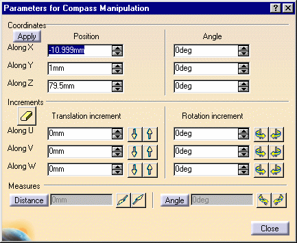
Double-click the shuttle in the specification tree (shuttle.1).
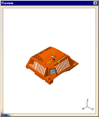
The Edit Shuttle dialog box, the Preview window and the Manipulation pop-up toolbar appear. 
Manipulation toolbar

-
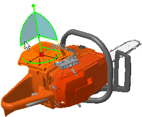
The 3D compass snaps to the shuttle axis.
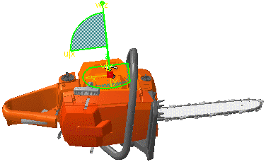

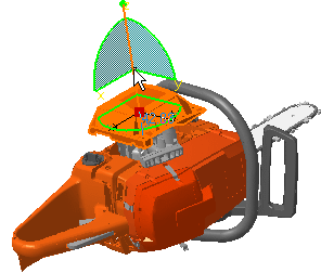
The move shuttle option is activated by default, which means that both the shuttle axis and geometry move together. -
Click the z axis on the 3D compass.
-
Drag the cursor to the shuttle's desired location.
-
Click the x plane on the 3D compass.
-
Drag the cursor to the left.
-
Use Reset
 when needed.
-
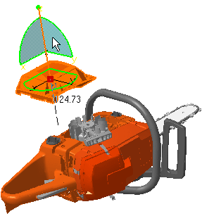
Select the z axis and drag the 3D compass.
-
Drag the cursor to the shuttle's desired location.
-
Rotate the shuttle by dragging an arc of the compass.
For example, drag the arc x z to the left, rotates the shuttle in the plane subtended by the arc x z: 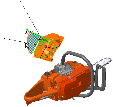
-
Click Reset
 .
.Now, you are going to use Smart Target 
-
Move the shuttle.1 as shown below.
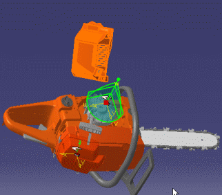
Reposition the shuttle (startinghouse) as it was -
Click Smart Target
 .
.- The shuttle is selected and highlighted in the geometry area
- Point the cursor on the first geometric element (a cylinder axis)
- Click the LMB.
- Select geometric element on the receiving component.
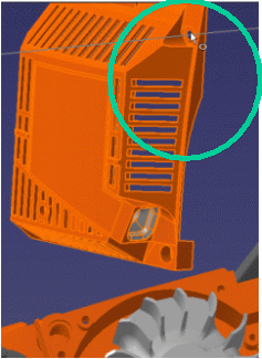
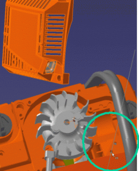
The first coincidence constraint is created. The shuttle is displaced in accordance with the first constraint.
You can continue directly to the creation of the second constraint.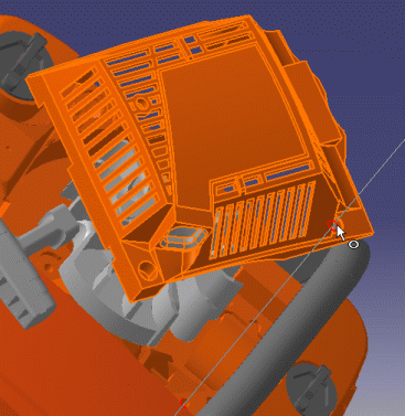
-
Create the second coincidence.
- Select a geometric element on the shuttle (point the cursor) e.g. the left hole axis as shown below
- Click the mouse button.
- Select a geometric element on the receiving component, a hole axis (right picture)
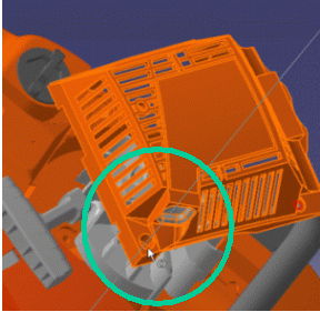
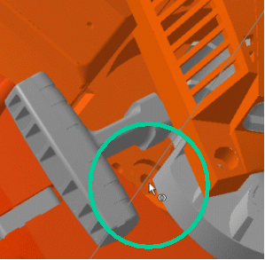
The second coincidence constraint is created. The shuttle is displaced in accordance with the second constraint. You can continue directly to the creation of the third constraint. 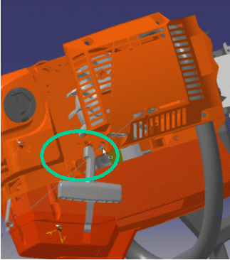
-
Create the third coincidence constraint.
- Select a geometric element on the shuttle e.g. a line on the shuttle as shown below
- Click the mouse button.
- Select geometric element on the receiving component, a line (right picture)
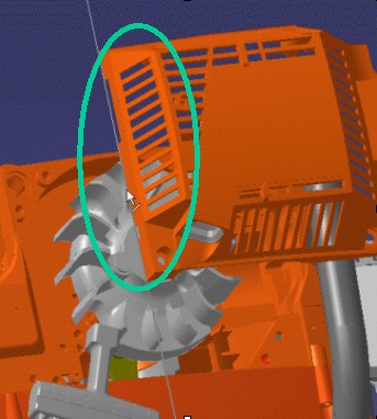
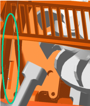
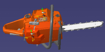
The third coincidence constraint is created. The shuttle is displaced in accordance with the third constraint. 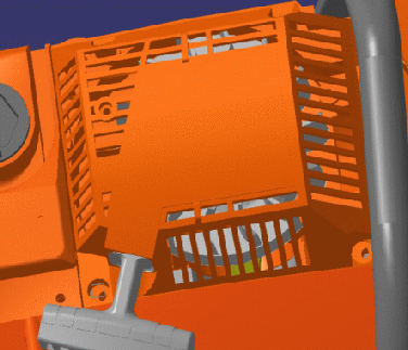
-
Click Smart Target
 to exit the command.
 -
Click OK in the Edit Shuttle dialog box.
