This section is only available with the SheetMetal Design products.
![]()
This section explains how to change the bend extremities, i.e. how to change axial relimitations for a straight bend.
-
Click Sheet Metal Parameters
 .
.The Sheet Metal Parameters dialog box is displayed. -
Click the Bend Extremities tab to access parameters defining bend extremities.

-
Choose a bend extremity, either from the drop-down list or using the graphical button underneath.
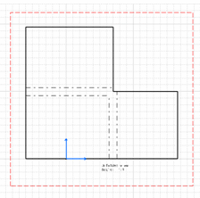
- Minimum with no relief (default option): the bend corresponds to the common area of the supporting walls along the bend axis, and shows no relief.
- Square relief: the bend corresponds to the common area of the supporting walls along the bend axis, and a square relief is added to the bend extremity. The L1 and L2 parameters can be modified if needed.
- Round relief: the bend corresponds to the common area of the supporting walls along the bend axis, and a round relief is added to the bend extremity. The L1 and L2 parameters can be modified if needed.
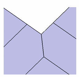
- Linear: the unfolded bend is split by two planes going through the corresponding limit points (obtained by projection of the bend axis onto the edges of the supporting walls).
- Tangent: the edges of the bend are tangent to the edges of the supporting walls.
- Maximum: the bend is calculated between the furthest opposite edges of the supporting walls.
- Closed: the bend corresponds to the intersection between the bends of two supporting walls. The closed bend extremity lies on the surface of the encountered bend.
- Flat joint: the two bends are joined in flat view.


-
Click OK to validate.
![]()