Geometric Modeler |
Topology |
How to Associate Topology With GeometryRules Between Topological and Geometric Objects |
| Technical Article | ||
AbstractThe topology describes the limitation of a geometry. Hence, topological objects are related to geometric objects within specified rules, which are detailed here |
The topology is a building set for limiting the space. Vertex bound edges, which bound faces, which bound volumes. How to map these topological entities to geometric entities in order to limit the geometric space?
[Top]
Consider the intersection curve of two surfaces. From the topological point of view, its geometry is represented by a CATEdgeCurve. From a geometric point of view, this curve may be seen as a curve on the first surface or as a curve on the second surface.
Hence, a CATEdgeCurve is the geometric representation of the topological edge, which may be seen under several representations.
When the curve is not the result of an intersection, the CATEdgeCurve may contain CATCurves that are not CATPCurves.
[Top]
Consider now the intersection point of two CATEdgeCurves. From the topological point of view, its geometry is represented by a CATMacroPoint. From a geometric point of view, this point may be seen as a point on the first edge curve (called CATPointOnEdgeCurve or POEC) or as a POEC on the second edge curve.
Hence, a CATMacroPoint is the geometric representation of the topological vertex, which may be seen under several representations.
When the curve is not the result of an intersection, the CATMacroPoint may contain CATPoints that are not CATPointOnEdgeCurves.
[Top]
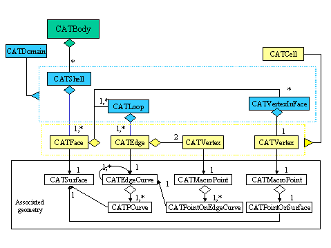
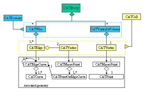
Here is detailed the precise rules of the geometry-topology relations, according to the type of domains that a cell bounds.
The geometric entity corresponding to a volume is the whole space, which is the same for all volumes. It is the reason why we do not have to precise it.
The geometric entity corresponding to a face is a CATSurface.
The geometric entity corresponding to an edge is a CATEdgeCurve. Imagine you want to use this CATEdgeCurve as geometry for the topology. Depending on how the edge is used to border (or not) a cell of higher dimension, the CATEdgeCurve will represent different types of curve.
[Top]
The geometric entity corresponding to a vertex is a CATMacroPoint. Imagine you want to use this CATMacroPoint as geometry for the topology. Depending on how the vertex is used to border (or not) a cell of higher dimension, this CATMacroPoint will represent different types of points.
[Top]
The following diagrams summarize the different configurations between the geometry and the topology.
 |
 |
[Top]
We suppose in all these examples that a CATGeoFactory and a CATBody have been already created. These examples only detail the cell construction. You must then create the domain (Lump, Shell, Wire, VertexInVolume) containing the cells and add it to the body to complete it. For code examples, see.
[Top]
[Top]
Note: A CATEdgeCurve cannot be directly created. Only its derived types (CATSimCurve, CATIntCurve, CATMergedCurve can be instantiated). For determining the choice of one of these objects, see About Edge Curves.
[Top]
[Top]
[Top]
This section details step by step the creation of a Wire containing one edge.
CATCartesianPoint * Point1=factory->CreateCartesianPoint(0,0,0);
CATCartesianPoint * Point2=factory->CreateCartesianPoint(0,10,0);
CATLine *           Line  =factory->CreateLine(Point1,Point2);
CATSimCurve * SimCurve =factory->CreateSimCurve(Line);
CATCrvParam       Param
CATCrvLimit       Limit = Line->GetLimits;
Limit.GetLow(Param);
CATPointOnEdgeCurve *
                   Poec1 = factory->CreatePointOnEdgeCurve(Line,Param,SimCurve);
Limit.GetHigh(Param);
CATPointOnEdgeCurve *
                   Poec2 = factory->CreatePointOnEdgeCurve(Line,Param,SimCurve);
CATMacroPoint      Macro1= factory->CreateMacroPoint();
Macro1->Append(Poec1);
CATMacroPoint      Macro2= factory->CreateMacroPoint();
Macro2->Append(Poec2);
CATVertex * Vertex1=body->CreateVertex();
Vertex1->SetGeometry(Macro1);
CATVertex * Vertex2=body->CreateVertex();
Vertex2->SetGeometry(Macro2);
CATEdge *   Edge= body->CreateEdge();
Edge->SetCurve(SimCurve);
Edge->AddBoundingCell(Vertex1,CATSideLeft,NULL,Poec1);
Edge->AddBoundingCell(Vertex2,CATSideLeft,NULL,Poec2);
CATWire Wire=body->CreateWire();
Wire->AddCell(Edge);
Body->AddDomain(Wire);
Note
: This was detailed for explaining all the capabilities of the topological objects. You can use operators such as CATWireOperator or CATSkinOperator to directly create domains from geometry.[Top]
[Top]
| [1] | The CGM Objects |
| [2] | Topology Concepts |
| [3] | The CGM Topological Model |
| [Top] | |
| Version: 1 [Mar 2000] | Document created |
| [Top] | |
Copyright © 2000, Dassault Systèmes. All rights reserved.