Analysis Solution

Analysis Modeler

Surface Mesher

The description of all attributes of the surface mesh part
Quick Reference

Abstract


The creation of a surface mesh part
: when user want to create a mesh part, he must give it's "late type" to indicate what type of mesh part he want to create, in this case the mesh part wanted is the surface one and it's late type is "MSHPartSmartSurf".

The following reference article shows the different attributes of a surface mesh part in two different ways: the geometric and the meshing attributes.
More over, in a third part local specifications of the mesh part will be detailed.


All geometric attributes of the surface mesh part

In order to mesh, surface must be prepared by simplification of the geometry. All attributes referenced in this part are managing this simplification. 

ConstraintSagValue


type: this argument is a double valuated to the  wanted sag.

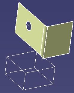
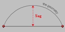
Attribute which specifies the geometric sag for the topology build.

On the right example, we can see that the required sag is biggest on the left picture than on the right one.

This attribute is linked to the size of the mesh, in other terms, the report between these attributes must be coherent. 

MinimumSize


type
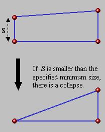
: this argument is a double valuated to the minimum size wanted for length of topological edges.

Attribute which specifies the minimum size accepted for the length of topological edges, under this size edges must be merged with others (if it's possible).

[Top]

FaceAngle


type
: this argument is a double valuated to the angle under which faces are grouped (radian). 


Attribute which specifies the minimum angle under which two faces from the geometry are grouped in a single topological domain (with usually other faces which fulfilled the same condition).

CurveAngle

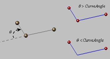
type: this argument is a double valuated to the angle under which edges are grouped (radian).

Attribute which specifies the minimum angle under which two edges from the geometry are grouped in a single topological edge.

DetailsElimination


type
: this argument is an integer valuated to,

  • 1 if user don't want to activate the merge of edges during the simplification of  the topology;
  • 2 if user want to activate the merge of edges during the simplification of  the topology.


Attribute which specifies that we activate the merge of edges during the simplification of the topology. This attribute is linked to the attribute "MinimumSize". In other terms, we try to merge edges which are smaller than the "MinimumSize" argument if this argument is active only.


[Top]

CleanSize

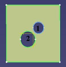
type: this argument is a double valuated to the minimum diameter under which a hole is ignored.

Attribute which specifies the minimum wide under which a hole is ignored.

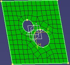
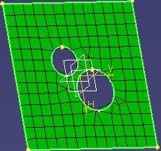
For  example in the right picture, a clean hole size was specified in the mesh part and the first hole was smallest than this value that's why it was ignored contrary to the second one which is biggest than this tolerance.

Offset

type: this argument is a double valuated to the offset between the geometry and the mesh.

Attribute which specifies the distance of the offset between the mesh and the geometry.

[Top]

OffsetFromThickness


type
: this argument is an integer valuated to,

  • 1 if user don't want to activate calculation of the offset from thickness between the geometry and the mesh;
  • 2 if user want to activate calculation of the offset from thickness between the geometry and the mesh.
Attribute which activates the calculation of the better offset between mesh and geometry when thickness was defined.

CurveCapture


type
: this argument is an integer valuated to,

  • 1 if user don't want to activate the capture of external curves;
  • 2 if user want to activate the capture of external curves.


Attribute which specifies if external curves must be captured (and consequently taking in account for the mesh). This attribute is linked to the attribute "CurveCaptureTol".

CurveCaptureTol


type
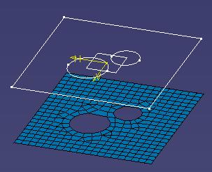
: this argument is a double valuated to the minimum distance under which we didn't capture external curves.


Attribute which specifies the maximum distance for curve capture: if a curve is farthest from the geometry than this tolerance, it was not captured even if the "CurveCapture" parameter is active. 

In the right picture, two different ways: the mesh part with curve capture attribute activated  but with a curve capture tolerance too small for the first picture.

[Top]

All meshing attributes of the surface mesh part

All attributes referenced in this part drive the mesh building. Some of its attributes are necessary for the build of the mesh, others are optimization attributes only.

GlobalSize


type: this argument is a double valuated to the wanted size for mesh elements (it is an objective).


Attribute which specifies the global size of the mesh ( it's an objective, meshers tried to approach nearest possible from this size).

GlobalMethod


type
: this argument is a CATUnicodeString valuated to,

  • "Frontal triangle" if user want to apply triangle mesh;
  • "Frontal quadrangle" if user want to apply quadrangle mesh.


Attribute which specifies the type of mesh element wanted by user. There is two different element type: quadrangle elements and triangle elements.

ElementOrder


type
: this argument is an integer valuated to,

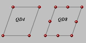
  • 1 if user want to mesh with linear elements ( TR3 or QD4 depending from global method choice);
  • 2 if user want to mesh with quadratic elements ( TR6 or QD8 depending from global method choice).

Attribute which specifies the type of elements we want to create, for example if the method selected is the quadrangle mesh, the two ways for element order are linear elements (QD4 in the right picture) or quadratic elements (QD8).

For more explanations see the Connectivity reference.

StripOptimization


type
: this argument is an integer valuated to,

  • 1 if user don't want to activate the optimization of mesh strip;
  • 2 if user want to activate the optimization of mesh strip.


Attribute which specifies if mesh in strips must be optimized in order to have a more regular mesh.

[Top]

MeshCapture


type
: this argument is an integer valuated to,

  • 1 if user don't want to activate the mesh capture;
  • 2 if user want to activate the mesh capture.


Attribute which specifies if external mesh must be captured. This attribute is linked to the attribute "MeshCaptureTol".

MeshCaptureTol


type
: this argument is a double valuated to the minimum distance under which we didn't capture the mesh.


Attribute which specifies the maximum distance for mesh capture: if a mesh is farthest from the geometry than this tolerance, it was not captured even if the "MeshCapture" parameter is active. 

MinimizeTriangles


type
: this argument is an integer valuated to,

  • 1 if user don't want to activate the minimization of the number of triangles;
  • 2 if user want to activate the minimization of the number of triangles.

Attribute which specifies if we try to minimize the number of triangles of the created mesh ( it is an optimization option).
WARNING: this attribute is useful when the global method is the quadrangle ( because the goal is to minimize the number of triangles by transformation) 

[Top]

OptimizeRegularity

type: this argument is an integer valuated to,

  • 1 if user don't want to activate the optimize regularity parameter;
  • 2 user want to activate the optimize regularity parameter.


Attribute which specifies if we activate the parameter of directional mesh; in other terms to decide to activate or not the parameter which favor a mesh direction for elements.
Example: On the right the first picture represent the mesh without direction for mesh and the second show the mesh with "Optimize regularity" parameter activated. In this case mesh around holes is more regular because driving by the direction of mesh (the calculation of this parameter is directed by the shape of the domain).

MeshAbsSag


type
: this argument is an integer valuated to,

  • 1 if user don't want to activate the mesh with a sag;
  • 2 user want to activate to activate the mesh with a sag.


Attribute which specifies if the mesh is created with an imposed minimum sag.
WARNING: this attribute is useful when the global method is the triangle one.

MeshAbsSagValue


type
: this argument is a double valuated to the wanted sag when "MeshAbsSag" attribute is activated.


Attribute which specifies the size of the maximum sag accepted, if the "MeshAbsSag" attribute is activated only. The sag specified is absolute and not associated to the mesh size. 
WARNING: this attribute is useful when the global method is the triangle one.

[Top]

MeshRelSag


type
: this argument is an integer valuated to,

  • 1 if user don't want to activate the mesh with a relative sag;
  • 2 user want to activate the mesh with a relative sag.


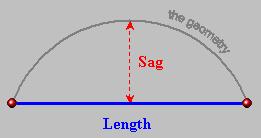
Attribute which specifies if the mesh is created with an imposed relative minimum sag (Sag/Length).
WARNING: this attribute is useful when the global method is the triangle one.

MeshRelSagValue


type
: this argument is a double valuated to the wanted relative sag when "MeshRelSag" attribute is activated.


Attribute which specifies the size of the maximum relative sag accepted. The relative sag is calculated by the quotient between the Sag and the length of the edge of a mesh element: Sag/Length.
WARNING: this attribute is useful when the global method is the triangle one.

MinSizeForSag


type
: this argument is a double valuated to the minimum size for elements even if the sag required a smaller size for mesh.


Attribute which specifies the minimum size for mesh. An "objective" size for mesh is specified ("GlobalSize" attribute) but the constrain sag required may implies the decrease of the mesh size in order to satisfy its condition, that's why this condition exist even if we try to approach the global mesh size wanted.
WARNING: this attribute is useful when the global method is the triangle one.

[Top]

All local specifications associated to the surface mesh part

Local specifications supports


For each local specification, what ever the type, a geometrical support must be associated to it. The following associated attribute must be set:

  • "Supports": A CATILinkableObject and a CATIProduct must be specified in order to define the support(s) of a local specification. Associated to the CATILinkableObject interface is a geometrical object represented by a Publication, a BREP...This geometrical object is different from each local specification. In the next parts, for each local specification, the type of geometrical object which is associated to the CATILinkableObject will be exposed.

Boundary Simplifications

MSHSuppressHole


type
: this specification is used in order to clean holes. Two associated attributes must be set:

  • "Status": this is a boolean which specify if the holes must be suppressed (1) or not (0);
  • "Supports": It must represent an edge of the hole to suppress and only one.


This attribute is used in order to specify holes which must be ignored for mesh generation. Note that they are no clean size like in automatic mode because user specify its own holes to be ignored. The utility of this attribute is to allow to user the possibility to ignore holes with another criterion than size.


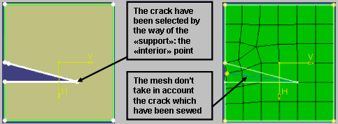
MSHSuppressCrack

type: this specification is used in order to ignore cracks of the geometry for mesh generation. Two associated attributes must be defined:

  • "Status": it is a boolean which define if the cracks must be ignored (1) or not (0).
  • "Supports": It must represent the vertex of the crack to suppress.


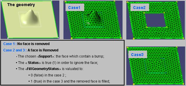
MSHSuppressFace

type: this specification is used in order to ignore faces of the geometry for mesh generation. Three associated attributes must be defined:

  • "Status": it is a boolean which define if faces must be ignored (1) or not (0);
  • "FillGeometryStatus": it is a boolean which define if faces must be filled (1) or not (0) after be removed;
  • "Supports": it must represent one or more faces (a connex set) to inactivate. Note that supports could be added more than one time in this case.


[Top]

Add\Remove Constraints

MSHConstrainEdge


type
: this specification is used in order to Constrain\Unconstrain edges from the geometry linked to the current mesh part. You must set two associated attributes:

  • "Status": it is a boolean which specify if  the support(s) must be constrained (1) or unconstrained (0).;
  • "Supports": it could represent one or more edges to inactivate. It could be also a set of faces from which edges to constrain will be extracted.


This attribute used in order to constrain or unconstrain edge(s) of the geometry associated to the current mesh part.

MSHConstrainVertex


type
: this specification is used in order to Constrain\Unconstrain a vertex from the geometry linked to the current mesh part. You must set two associated attributes:

  • "Status": it is a boolean which specify if  the support(s) must be constrained (1) or unconstrained (0).
  • "Supports": it must represent a vertex to constrain.


This attribute used in order to constrain or unconstrain vertex(ices) of the geometry associated to the current mesh part.


MSHConstrainCurve


type
: this specification is used in order to Constrain\Unconstrain curves from a geometry which is not linked to the current mesh part. You must set one associated attribute:

  • "Supports": it could represent one or more edges to inactivate. It could be also a set of faces from which edges to constrain will be extracted.


This attribute is used in order to specify external edges that user want to constrain for the current mesh part. For more explanations see the picture which explain how to use automatic curve constrain in the CurveCaptureTol part.


MSHConstrainPoint


type
: this specification is used in order to Constrain\Unconstrain a point from a geometry which is not linked to the current mesh part. You must set one associated attribute:

  • "Supports": it must represent a vertex to constrain.


This attribute is used in order to specify external point(s) that user want to constrain for the current mesh part.

[Top]

Imposed Elements

MSHDistributionElement

type: this specification is used in order to define a distribution on edge(s). In order to use it a lot of attributes must be defined:

  • "Symmetric": it is a boolean which specify if the distribution must by symmetric (1) or not (0) on the chosen support(s);
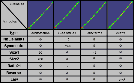
  • "Type": it is a string, which define the type of wanted distribution; there is four possibilities:
    • "Isometric";
    • "Geometric";
    • "Arithmetic";
    • "Law": defined by the way of a law set by user.
  • "Reverse": linked to the "Law" type, this attribute allow to apply its law in the reverse side of the edge than default one;
  • "Option": it is an integer from 1 to 8 which define the set of attributes to apply depending from the distribution type;
  • "NbElements": it is an integer which represent the number of elements wanted for the distribution;
  • "Size1"and"Size2": it is a length (double) which represent the distance from the first extremity (respectively the second) of the edge to the first internal node;
  • "Ratio21": it is a ratio (double) between Size1 and Size2 wanted sizes;
  • "Supports": it must represent a set of edges (continuous). Note that supports could be added more than one time in this case.


Linked to the choice of the distribution "type" is the set of parameter to apply to this distribution; you must choose the option number which define this set and define corresponding attributes. The next array show the different possibilities.

For example, if user choose an "Arithmetic" distribution type; there is six possible "Option" (set of parameters to apply) to choose:

  • The size to the first element from the first and the second node: the Option 8 must be chosen and attributes Size1 and Size2 must be defined;
  • The total number of elements and the ratio between Size1 and Size2: the Option 3 must be chosen and attributes NbElements and Ratio21 must be defined;
  • ...


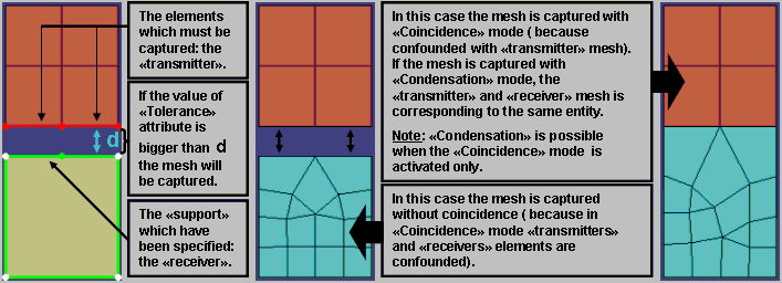
MSHCaptureElement


type
: this specification is used in order to define mesh capture coming from others mesh parts. In order to use it, others associated attributes must be defined:

  • "Tolerance": this is a length (double) which define the tolerance of the capture;
  • "Coincidence": this is a boolean which define if the capture must be done with (1) or without (0) coincidence;
  • "Condensation": this is a boolean which define if the capture must be done with (1) or without (0) condensation;
  • "Sources": to this component you must set the capture source if no tolerance have been set.
  • "Supports": it must represent a set of edges. Note that supports could be added more than one time in this case.

Using: there is two solutions:

  • Specify a capture tolerance size with the "Tolerance" attribute;
  • Specify a set of mesh transmitters supports with the "Sources" attribute.


[Top]

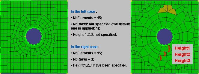
 MSHMeshAroundHole


type
: this specification is used in order to apply a mesh distribution around  a set of holes. A lot of attributes must be defined:

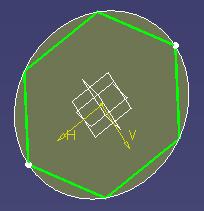
  • "NbElements": it is an integer which define the number of elements (mesh edges) to create around each hole of the set specified;
  • "NbRows": it is an integer {1,2,3} which define the number of rows of mesh elements to create around the hole;
  • "Height1", "Height2" and "Height3": these attributes depends from the NbRows attribute. You must define these ones to specify the height of each row elements:
    • if NbRows = 1 (default case), you can specify Height1;
    • if NbRows = 2, you can specify Height1 and Height2;
    • if NbRows = 3, you can specify Height1, Height2 and Height3;
  • "Supports": it must represent an edge only.


Note that the specification which define the number of rows of elements to mesh around the hole is ignored if the default mesh is the frontal triangle one. This specification is available with frontal quadrangle mesh only.

[Top]

Domain Specifications

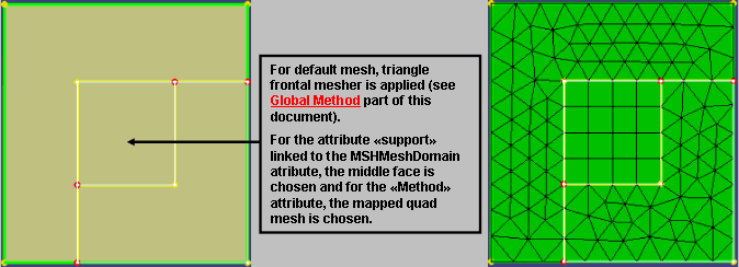
MSHMeshDomain


type
: this specification is used in order to specify a mesh method to a topological domain. Three attributes associated to this one must be defined:

  • "Method": it is a string which define the type of mesh method to apply in the selected supports;
  • "Size": it is a length (double) which specify the mesh size wanted.
  • "Supports": it must represent a connex set of faces.


What about the different mesh methods which could be applied ?


The names specified upper each picture is corresponding to the
"Method" name which must be define in "MSHMeshDomain"
 specification.


History

Version: 1 [Mar 2004] Document created.
[Top]

Copyright © 2004, Dassault Systèmes. All rights reserved.