Analysis Solution

Analysis Modeler

Octree Mesher

The description of all attributes of the Octree mesh part

Quick Reference

Abstract


The creation of an Octree mesh part
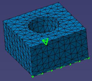
: when user want to create a mesh part, he must give it's "late type" to indicate what type of mesh part he want to create, in this case the mesh part wanted is the Octree one and it's late type is "MSHPartOctree3D" for a tri-dimensional mesh (to mesh a solid with tetrahedron elements) and "MSHPartOctree2D" for a surface mesh (to mesh a surface with triangle elements).

The following reference article shows the different attributes of an Octree mesh part.
There is two different categories of attributes: global and local ones associated to the Octree mesh part.

 The Attributes:

The Local Specifications:

Local specifications supports


All attributes of the Octree mesh part

All attributes referenced in this document drive the octree mesh and define precisely what type of mesh is wanted by user.   

SizeValue


type: this argument is a double valuated to the wanted size for mesh elements (it is an objective).


Attribute which specifies the global size of the mesh ( it's an objective, Octree mesher tried to approach nearest possible from this size).
WARNING: the size value is the objective size for "skin" mesh, for 3-dimensional mesh user must give an interior size, else 3D Octree mesher tried to create interior element as biggest as possible. 

ElementOrder


type
: this argument is an integer valuated to,

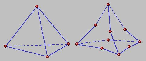
  • 1 if user want to mesh with linear elements (TR3  or TR4 depending from the type of Octree mesh part: 2D or 3D);
  • 2 if user want to mesh with parabolic elements (TR6 or TR10).

Attribute which specifies the degree of elements that user want to create: there is two possibilities, linear elements (TR3 or TR4 depending from the Octree mesh part type (2D or 3D)) and parabolic elements (TR6 or TR10).
[Top]

MaxWarpAngle


type:this argument is a double valuated to the  wanted max warp angle for elements (radian).


Attribute which specifies the maximum warp angle accepted for a quadratic triangle element.

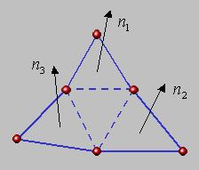
Explanations: for a quadratic triangle element the warp angle is the maximum angle between two normals of a couple of sub-triangles (formed by the connection between nodes and intermediate nodes). In the right example the maximum warp angle of the element is:

[Top]

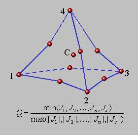
MinJacobian


type: this argument is a double valuated to the wanted minimum size for Jacobian value for each  element.


Attribute which specifies the minimum Jacobian accepted for each element of the mesh.

[Top]

ProportionalSag


type: this argument is an integer  valuated to,

  • 1 if user don't want to apply mesh with proportional sag;
  • 2 if user  want to apply mesh with proportional sag. 


Attribute which specifies if the mesh is created with an imposed proportional minimum sag. This attribute is linked to the "ProportionalSagValue" attribute.

ProportionalSagValue

type: this argument is a double valuated to the wanted proportional sag. 

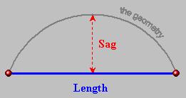
Attribute which specifies the size of the maximum relative sag accepted, this attribute is active when the "ProportionalSag" attribute is active only. The relative sag is calculated by the quotient between the Sag and the length of the edge of a mesh element: Sag/Length.

[Top]

AbsoluteSag


type
: this argument is an integer  valuated to,

  • 1 if user don't want to apply mesh with absolute sag;
  • 2 if user  want to apply mesh with absolute sag. 


Attribute which specifies if the mesh is created with an imposed absolute minimum sag. This attribute is linked to the "AbsoluteSagValue" attribute.

AbsoluteSagValue

type: this argument is a double valuated to the wanted proportional sag. 

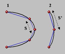
Attribute which specifies the size of the maximum absolute sag accepted, this attribute is active when the "AbsoluteSag" attribute is active only. The maximum size of the sag is imposed and contrary to the proportional sag this one doesn't take in account the "local" size of the mesh: in other terms if the curvature radius of the geometry is big, the imposed sag can imply a very small size for the mesh.

Example: in the right picture the curvature radius is biggest in the first case, that's why, in order to satisfy the imposed sag condition, the size of the mesh is smaller than in the second case.

[Top]

Criteria


type
: this argument is an integer  valuated to,

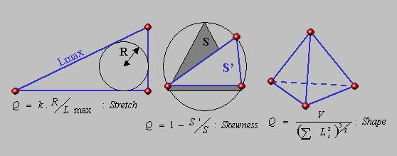
  • 1 if user want to respect "Skewness" factor for the mesh;
  • 2 if user want to respect "Stretch" factor for the mesh;
  • 3 if user want to respect "Shape" factor for the mesh.

Attribute which specify the factor that user want to respect for the elements of the mesh. Octree mesher provide the possibility for user to control one of these arguments.

[Top]

MinGeometrySize


type: this argument is a double valuated to the wanted minimum size under which geometry is ignored for mesh specifications.


Attribute which specifies the minimum size for considered geometry: in other terms, under this size geometry is not taking in account for the mesh.

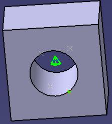
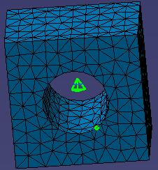
The right example represent a small face ( edges which formed this face are smaller than the required minimum geometry size). For octree mesher this face is assimilated to a point (see the right picture).

[Top]

MinSizeForSags


type
: this argument is a double valuated to the minimum size for elements even if the sag required a smaller size for mesh.


Attribute which specifies the minimum size for mesh. An "objective" size for mesh is specified ("SizeValue" attribute) but the constrain sag required may implies the decrease of the mesh size in order to satisfy it's condition, that's why a minimum size condition exist even if the Octree mesher tries to approach the global mesh size specified.

[Top]

MeshGeometryViolation


type
: this argument is an integer  valuated to,

  • 1 if user don't want to apply a minimum size for mesh elements;
  • 2 if user  want to apply a minimum size for mesh elements.


Attribute which specifies the minimum size for a mesh edge, in order to optimize the regularity of the mesh, user can apply the suppression of small mesh elements by activation of this attribute. 

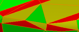
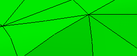
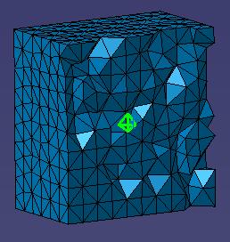
The right example show the difference between an octree mesh without mesh edges suppression (the highest picture) and with the suppression of smallest mesh edges.

[Top]

InteriorSize


type
: this argument is an integer  valuated to,

  • 1 if user don't want to apply an imposed maximum interior size for mesh;
  • 2 if user  want to apply an     maximum imposed interior size for mesh. 

WARNING: this attribute is active when the part is an octree 3D only (because interior size has no sense for surface mesh).


Attribute which specifies if user want to apply an imposed maximum size for the interior size of the 3D mesh; because, by default, Octree mesher tried to mesh the interior of the solid as biggest as possible. This attribute provide to user the possibility to limit this expansion by imposing a maximum size.
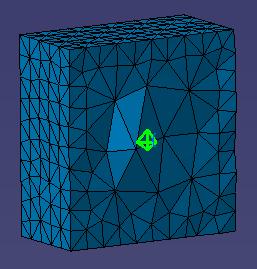
Example: On the right example, the first picture represent the mesh without imposed interior size contrary to the second one where the interior size was imposed at the same size than the global mesh size (the mesh is more regular) .

[Top]

MaxInteriorSize


type
: this argument is a double valuated to the wanted proportional sag. 


Attributes which specifies the value of the imposed interior size for 3D mesh when the "InteriorSize" attribute is active.

[Top]

MaxAttempts


type: this argument is an integer valuated to the number of attemps for launching Octree algorithm if the mesh of the solid failed.


Attribute which specifies the maximum number of attempts to launch the Octree algorithm if the mesh has failed.

  [Top]

All local specifications of the Octree mesh part

Local Specifications supports


These specifications adhere to CATISamAnalysisEntity interface. For each one, a geometrical support must be set (it is the default behavior) as explained in the documentation about CATISamAnalysisEntity interface. More over, authorized supports must be defined.

For each following local specification, the additional parameters will be detailed and the authorized supports types will be defined.

MSHLocalMeshSize


type: this specification is used in order to specify a local mesh size to faces or edges of the geometry: you must set a parameter associated to this attribute:

  • "MSHMeshSizeMag": it is a length (double).

Authorized supports: 1D or 2D supports are authorized


Specification  which define a local size for mesh in a set of faces or edges.

[Top]

MSHLocalMeshSag


type: this specification is used in order to specify a local mesh sag to faces or edges of the geometry: you must set a parameter associated to this attribute:

  • "MSHMeshSagMag": it is a length (double).

Authorized supports: 1D or 2D supports are authorized.


Specification  which define a local sag for mesh in faces of edges. See also the definition of the sag.
 

[Top]

MSHLocalMeshImposedPoints

type: this specification is used in order to impose mesh (nodes) on points of the geometry.

Authorized supports: 0D supports are authorized only.

Specification which specify imposed nodes of the mesh.


[Top]

MSHLocalMeshDistribution


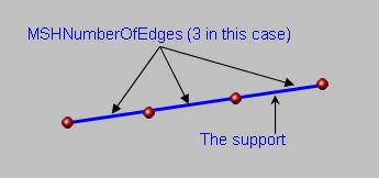
type: this specification is used in order to impose a mesh distribution on  edges of the geometry, you must set a parameter associated to this attribute:

  • "MSHNumberOfEdges": it is an integer which specify the number of mesh edges wanted on the specified geometry.

Authorized supports: 1D supports are authorized only.


Specification which specify an imposed mesh distribution on edges of the geometry.


History

Version: 1 [Mar 2004] Document created.
[Top]

Copyright © 2004, Dassault Systèmes. All rights reserved.