
AbstractThis article discusses the Part Design features. To take full advantage of this article, a pre-requisite knowledge of the Mechanical Modeler [1] is essential. |
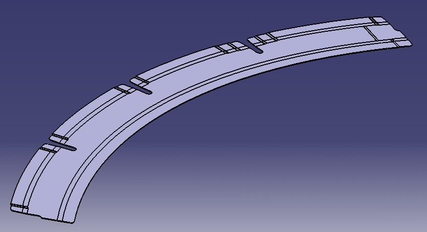
It is a Mechanical Feature designed to create surfacic sheet metal parts. The specificity of these type of parts is that they consist of a complex surface with a small thick.
Sheet Metal Features have two associated views : a Folded view and an UnFolded view :
Each Sheet Metal Feature may be considered as a set of 2 Mechanical Features ( 1 per view ). An Aerospace Sheet Metal Feature is a set of Sheet Metal Features. This internal model complexity explains that it is possible that you need to call specific method to update internal Features links (i.e. : Joggle : ManageOnSupport method) and that we suggest to update the Part instead of the Aerospace Sheet Metal Feature.
[Top]
A Web Feature is the base feature for all Aerospace Sheet Metal Feature. Only one Web can exist in a Part.
A Web Feature is a bounded planar surface. Next developpments should enable a non-planar surface.
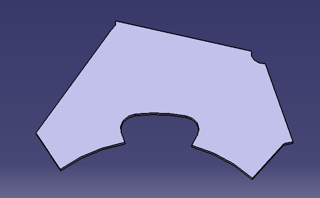
The Web internal Model consists of :
a SUPPORT : the Surface on which the Web will be created.
a BOUNDARY : a set of Limits : Curves , Surfaces or a closed Sketch.
If a Limit is a Curve it will be projected on the Support Surface.
If a Limit is a Surface it will be intersected with the Support Surface.
The set of resulting Curves on the Support must represent a closed Wire ( the BOUNDARY ).
[Top]
A Surfacic Flange Feature is a Feature that stiffen the Part.
This Feature consists of a bounded Surface intersecting the Web or another Surfacic Flange.
The intersection between the Surfacic Flange and its Base Feature (IWBF) is filleted.
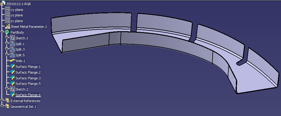
The sample above shows a Web bounded by five Surfacic Flanges.
The Surfacic Flange internal Model consists of :
a BASE FEATURE : the Web or another Surfacic Flange.
a SUPPORT : a Surface or a Curve which will be bounded by :
an EDGE OF PART (EOP) : a Curve or a Length limiting the opposit side to IWBF.
two SIDES : a Surface or a Curve defining left and right sides.
Some technological attributes : Bend Radius, Manufacturing Process, Compensation ...
The set of resulting Curves (IWBF, SIDE 1, EOP, SIDE 2) must represent a closed Wire (the Support boundary).
[Top]
A Joggle Feature is a local deformation ( twist ) of a Surfacic Flange or a Web.
This Feature consists of an offset (Depth) of its Support Surface (Surfacic Flange or Web) The Support Surface and the Offset Surface are joined by a ruled Surface (Runout).
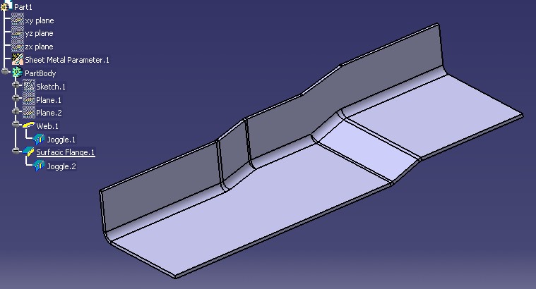
The sample above shows a Joggle on Web and a Joggle on a Surfacic Flange.
The Joggle internal Model consists of :
a SUPPORT : the Web or a Surfacic Flange.
a PLANE : a CATPlane or a Planar Face defining the start of the Joggle.
the DEPTH : distance between the Support Surface and its offset Surface.
the RUNOUT : the Joggle Length.
the START RADIUS : Radius of the Fillet between between the Support Surface and the Runout.
the END RADIUS : Radius of the Fillet between between the offset Surface and the Runout.
The specificity of the Joggle is that it can not be isolated : a Joggle is always immerged in its Support Model ( like a contextual Feature ). A Joggle will thus be automatically deleted (desactivated) if its Support is deleted (desactivated).
[Top]
| [1] | Mechanical Modeler Overview |
| [Top] | |
This article has explained what is an Aerospace Sheet Metal Feature and has given a description of them.
[Top]
| Version: 1 [January 2005] | Document created |
| [Top] | |
Copyright © 1994-2005, Dassault Systèmes. All rights reserved.