 |
This reference describes the weld
creation/edition dialog box and its related tabs. |
|
|
| |
Fillet Weld Parameters
|
| |
 |
| |
Main Characteristics
|
| |
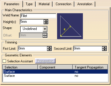
Defines the weld main
characteristics:
- Weld Name identifies the weld feature.
- Height specifies the weld's height.
- Shape provides five options to define the weld's top face.
- Undefined (default option)
- Flat
- Convex
- Concave
- Smooth
- Offset specifies the weld's offset for convex or concave
shapes only.
|
| |
Trimming
|
| |
Defines how the fillet weld is
trimmed:
- First Limit defines the first limit for the trim.
- Second Limit defines the second limit for the trim.
|
| |
Geometric Elements
|
| |
Defines the geometries needed to
create the weld:
- Selection Assistant option defines whether the weld's
Assistant Viewer window is displayed or not to help you select the
geometry you need.
This option displays a window showing you the geometric elements required
to compute the weld. Zoom in or resize the window to improve the view if
need be.
To close that window, just uncheck the option.
- Propagation command allows you to propagate the fillet weld
on a selected geometry in the table.
- The table lets you define and show the geometries needed to create the
weld:
- Selection column shows the type of geometry to be
selected.
- Component column shows the component related to the
selected geometry.
- Tangent Propagation column shows whether the fillet weld
is propagated by tangency on the selected geometry.
|
| |
Other Weld Parameters
|
| |
 |
| |
Main Characteristics
|
| |
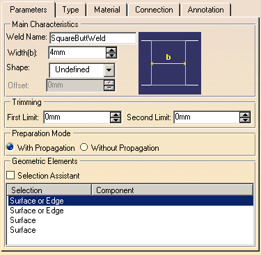
Defines the weld main
characteristics:
- Weld Name identifies the weld feature.
- Width specifies the weld's width.
- Shape provides five options to define the weld's top face.
- Undefined (default option)
- Flat
- Convex
- Concave
- Smooth
- Offset specifies the weld's offset for convex or concave
shapes only.
|
| |
Trimming
|
| |
Defines how the fillet weld is
trimmed:
- First Limit defines the first limit for the trim.
- Second Limit defines the second limit for the trim.
|
|
Preparation Mode |
| |
Determines how you want to remove
joining parts material along the edges.
- With Propagation option removes material along the entire
edges.
- Without Propagation option removes material just along the
portion of edges used for making the bridge between the joining parts.
|
| |
Geometric Elements
|
| |
Defines the geometries needed to
create the weld:
- Selection Assistant option defines whether the weld's
Assistant Viewer window is displayed or not to help you select the
geometry you need.
This option displays a window showing you the geometric elements required
to compute the weld. Zoom in or resize the window to improve the view if
need be.
To close that window, just uncheck the option.
- The table lets you define and show the geometries needed to create the
weld:
- Selection shows the type of geometry to be selected.
- Component shows the component related to the selected
geometry.
- Tangent Propagation shows whether the fillet weld is
propagated by tangency on the selected geometry.
|
| |
Weld Type
|
| |
 |
| |
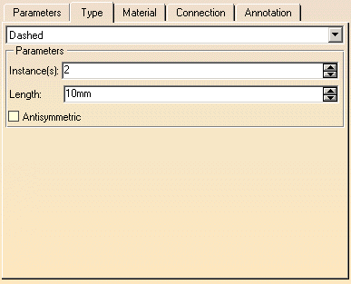
Two options are offered:
- Simple defines a continuous weld.
- Dashed defines a dashed weld.
|
| |
Parameters
|
| |
Available with the dashed type
option only. Defines the dashed type parameters:
- Instances defines the number of beads to be created.
- Length defines the length for each bead.
- Antisymmetric defines whether the beads are non-symmetric,
for double weld only.
|
| |
Weld Material
|
| |
 |
|
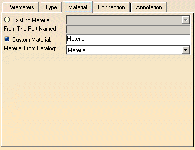
Two options are offered:
- Existing Material option allows you to retrieve a material
specified in an existing weld related with the selected parts:
- The available materials are listed in the combo list.
- From the part named field displays the part containing
the material, read-only.
- Custom Material option allows you to assign a material to
the weld from a list or to name a new one:
- The material name field allows you to customize it.
- Material from catalog combo list displays materials
available from the application.
|
 |
At any time you can modify the
material assigned to an existing part. |
| |
Weld Connection
|
| |
 |
|
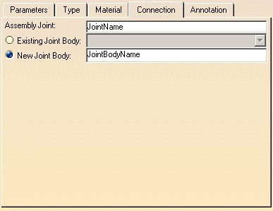
- Assembly Joint defines the joint name under which you will
place the weld in the specification tree. If the application has detected
that a joint comprising the reference geometry you selected already
exists, the name of this joint is displayed in the field and cannot be
changed.
Two options are offered:
- Existing Joint Body option allows you to select the
desired joint body from the combo list. If the product instance contains
no existing joint bodies, it is not possible to check this option.
- New Joint Body option allows you to enter a name for the
joint body if you want to create a dedicated joint body.
|
|
|
Weld Annotation
|
| |
 |
|
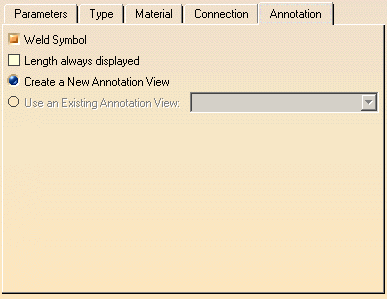
- Weld symbol option defines whether a weld annotation
is created.
This option is persistent for the next weld creation.
- Length always displayed option defines whether the
weld length is displayed in the weld annotation.
Available if the Weld symbol option is selected only.
- Create a new annotation view option creates a new
annotation view to set the weld annotation. This annotation view is
created in product instance containing the related parts with the weld.
Available if the Weld symbol option is selected only.
- Use an existing annotation view option allows you to
reuse existing
annotation views to set the weld annotation. These annotation views belong
to the product instance containing the related parts with the weld.
Available if there is an existing annotation view at least and if the Weld symbol option
is selected only.
|


