-
Click the Single-V Butt Weld with Broad Root Face Creation icon:

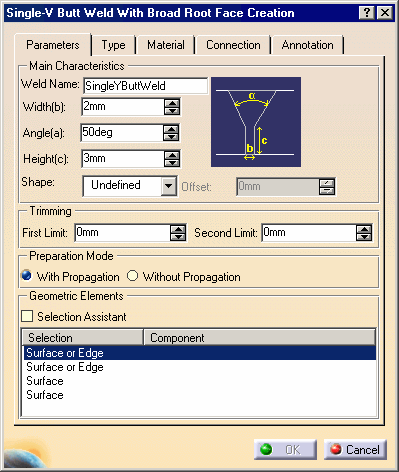
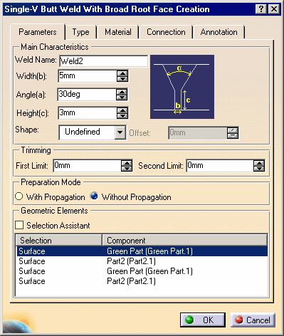
The Single-V Butt Weld With Broad Root Face Creation dialog box is displayed:
-
Enter Weld2 to identify the new weld.
-
Enter 5mm as the weld's width.
-
Enter 30deg as the weld's angle.
Selection Assistant
-
Check the Selection Assistant option.
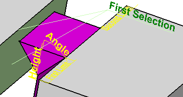
If necessary, zoom in the view area to improve the view. The "First Selection" text points to a face and an edge meaning that you have the choice between selecting a face or an edge.
-
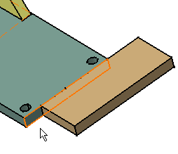
Select the green face in contact with Part 2.
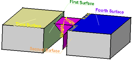
Note that the view area now shows the four selections required to weld the components.
-
Select the brown face in contact with the face that you have just selected.
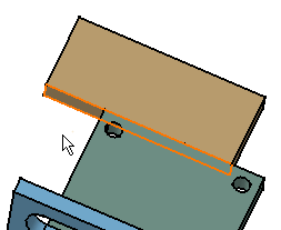
-
Select the last two faces as shown:
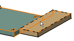
Connection Tab
-
Click the Connection tab to access additional options.
-
Give a new name for the assembly joint. A joint is a set of the components which geometry is used for creating welds: for example, enter Single-V Butt Joint in the Assembly Joint field.
-
Give a new name for the New Joint Body: Single-V Butt Joint Body for example.
Material Tab
-
Click the Material tab to define the material you wish to assign to the fillet weld.
-
Select Copper from the Material From Catalog list.
-
When done, click OK to create the Single-V Butt weld. The copper weld part as well as the corresponding annotation are created.
Note that the edges of the parts have been cut in a particular way.
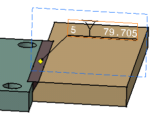
Annotation Tab
-
Click the Annotation tab to define the weld annotation.
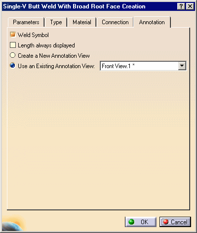
The previous created annotation view is pre-selected.
-
Keep options as is.
Specification Tree
-
Expand the Product2 node.
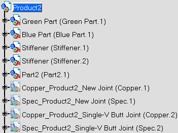
Two new parts have been created and are displayed in Hide mode:
-
Copper_Product2_Single-V Butt Joint(Copper.2): includes the geometry of the weld shape.
-
Spec_Product2_Single-V Butt Joint(Spec.2): includes the geometry used to compute the weld.
-
Expand the Assembly Joints node.
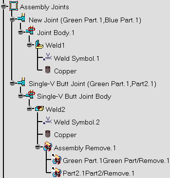
The Assembly Joints node now includes new elements:
-
 Single-V Butt Joint (Green Part.1, Part2.1) comprising Green Part.1
and Part2.1.
 -
 Single-V Butt Joint
Body gathers all joint elements.
 -
 Weld2:
indicates the weld's name.
 -
 Weld Symbol.1: indicates the annotation.
 -
 Copper: indicates the material assigned to the weld.
 -
 Assembly Remove.1: assembly remove feature comprising the
components which material has been removed to create the weld.
 -
 Green
Part.GreenPart/Remove1: part remove feature for Green Part.1.
-
Expand the Annotation Set.1 node.
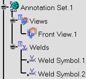
The Annotation Set.1 node now includes a new element:
-
 Weld Symbol.2: indicates the annotation.
For more detailed information about the Single-V Butt Weld command, please refer to the reference task Creating a Single-V Butt Weld with Broad Root Face.