 |
This task explains how to measure
distance between various elements.
|
 |
1. |
With your document open, select the Measure
Distance/Angle of 3D Systems button
 .
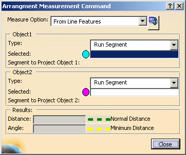
The Arrangement Measurement Command dialog box displays. .
The Arrangement Measurement Command dialog box displays.
 |
 |
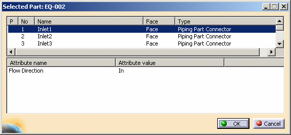
The Select Part to Display
Connector List button allows you to select a connector from a dialog
box, which can be useful in busy situations, as well as get information
about the connector. The button is either toggled on or off. To enable it, select
the button. When you select a part a dialog box appears showing all
connectors on that part, and the connectors display on the part (the
dialog box displays only when the object type selected is connector).
Select a connector in the dialog box - the selected connector is orange
on the part.
Note: The dialog box only displays if you select "connector" as the type
of Object 1 or Object 2 or both.
When the distance is displayed as a dashed green line it means it is
calculated normal to the plane. When it is a dashed yellow line then the
minimum distance has been calculated. |
|
2. |
You need to select a Measure Option and then the two
objects for measuring distance. The Measure Option provides three
options:
From Line Features: Select this if you are measuring distance between
a run segment, line or connector. Note that a connector will only be
considered a line if it is Object 1. A connector selected as
Object 2 is
always considered a point. If you use this option then the distance will
only be calculated if the angle between the two objects is between 0 and
5, and 175 and 180 degrees. If the angle is outside this range then the
distance will not be calculated - only the angle will be.
Along a Run: Select this to measure distance along a run.
Connectors or Nodes: Select this to measure distance between
connectors or nodes. All three Measure Options are explained below.
The procedures described below are for some elements - use the same
procedures for other elements also. |
|
3. |
Select From Line Features as the Measure Option and Run
Segment for both Object 1 and 2. Make sure Run Segment for Object 1 is
highlighted and select the run segment in your document. Do the same for
Object 2. The Distance field in the Results pane displays the distance.
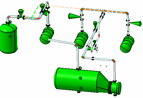

The distance is measured by extending a straight line from Object
2 so that the green dashed line can be drawn to Object 1 at a 90 degree
angle, and then calculating the distance. This is shown in the image. |
| |
4. |
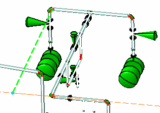
Select From Line Features as the Measure Option and
Connector for both Object 1 and 2. The Object 1 connector is treated as
a line and the Object 2 connector as a point. To measure, a line is
drawn through the Object 1 connector - along its vector - and a 90
degree line drawn to it from Object 2 for calculating the distance. The
distance displays in the Results pane.
 |
| |
5. |
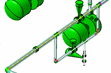
Select Along a Run as the Measure Option and Connector for
both Object 1 and 2. You can measure distance on the same run using this
method, by selecting node, point, connector or face. You can also
project a node from another location onto the run you are measuring. To
measure from one location to another location on the same run: Select
one of the elements mentioned for Object 1, in this case connector. The
Segment to Project Object 1 is automatically filled in, showing the
segment to which the element is
linked. Select a second element as Object 2. The Segment to
Project Object 2 field is automatically filled in, a yellow dashed line
displays along the run, and the distance displays in the Results pane.
Also, blue and magenta dots display at the start and end locations.
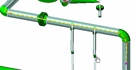
To project an element and use the projection for measuring:
- Select Object 1, in the example below it is a node.
- Select a segment if the Segment to Project Object 1 field is not
automatically filled in.
- Select Object 2, which is the object you want to project. In the
example below it is a connector located where the mouse pointer is.
- Select the segment on to which you want to project it. A magenta
dot shows at the location where it is projected, a dashed yellow line
displays in the selected portion and the distance is displayed in
the Results pane.
|
| |
6. |
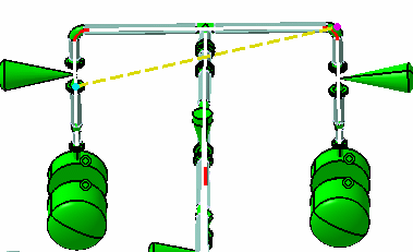
Select Connector or Node as the Measure Option and
Connector or Node for Object 1 and 2. In the example below connector to
node distance is measured. Select Connector in the Object 1 field and
select a connector. Do the same for a node for Object 2. A yellow dashed
line displays between the two and the distance displays in the Results
pane.
 |
|
 |