In addition to adding insulation to a part, some of the functionalities described here are:
Click the Insulation
Management button
![]() and the
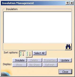
Insulation Management dialog box displays.
and the
Insulation Management dialog box displays.
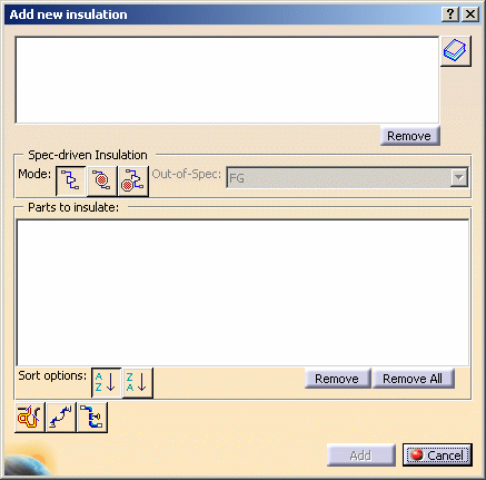
Select the mode. In the example below the Non-spec mode has been selected. The procedure of adding insulation parts is similar for all three modes. The difference between the three modes is explained below.
Select the parts in your document to which you want to add insulation. The part names display in the Parts to Insulate pane. To add more than one part use the Control key.
Double-click on the insulation part you want to add.
The Add New Insulation dialog box redisplays with the selected insulation part displaying in the top pane.
Repeat this process for each insulation part you want to add.
NOTE: You should note that you can apply more than one insulation part to a part. Therefore, ALL the insulation parts you select will be applied to ALL the parts that display in the Parts to Insulate pane (when you click the Add button).
Click Add in the Add New Insulation dialog box when you are done. The Insulation Management dialog box displays again, with the insulation parts you selected shown in the Insulation pane.
Notice that the parts you selected are highlighted in your document and in the specifications tree. The selected insulation parts listed in the Insulation pane now are added to these parts.
Click Close to close the dialog box.
DISPLAYING INSULATION PARTS: When you place an insulation part, and a graphic representation is not defined as explained below, you cannot see it. If the insulation part is placed on a light part, to make it visible click the Show button in the Insulation Management dialog box after you have placed the part. In this case a graphic representation is not needed.
If the insulation part is placed on a heavy part, to make it visible you have some options. In all cases you must first make sure that the base part on which it is placed has a graphic representation defined. This is because the insulation part uses the graphic representation defined for the base part.
You can then follow one of two methods. One is to add a value for the attribute Graphic Representation Name when you are building the insulation part. Make sure that the value is the same as one of the values defined for the base parts you will be placing insulation on. If you want the Envelope graphic representation to display, then the base parts should have a graphic representation named Envelope defined.
If you have not done this you can use another method. Right-click on the insulation part in the specifications tree and select Properties. In the Properties dialog box (Multi-Discipline tab), enter a value in the Graphic Representation Name field - again, this should be one that has also been defined for the base part. The Envelope value provided with this application can be used, or you can use one you have created. You can now use the Show and No Show buttons to display or hide the insulation.
To learn more about graphic representations see Building Parts > Defining Graphic Representation for a Part. Also see Creating a Part.
Non-spec mode: No insulation specification is taken into account. The thickness of the insulation part is the thickness that was defined when the part was created.
In-spec mode: The thickness of the insulation part is calculated, based on the part size, and the attributes temperature and insulation specification. Part size is defined on the part, and the two attribute values are obtained from the line.
Out-of-spec mode: You can select a specification other than the one that was defined for the line. When you click the Out-of-spec button the Out-of-spec field becomes available. Select a specification in this field. The insulation thickness will be calculated using this specification. NOTE: The specifications shown in this field are obtained from the XXXInsulationSpecifications Catalog, where XXX is the discipline, like Piping. The default location is at ...EquipmentAndSystems\XXX\InsulationSpecification where XXX is a discipline, like Piping.
Click the Insulation Management button. Select a part with insulation parts defined. The insulation parts display in the Insulation pane in the Insulation Management dialog box.
From the Insulation pane, select the insulation parts you want to add to other parts, and click the Insulate button. The Add New Insulation dialog box displays.
Select other parts in your document. The selected parts display in the Parts to Insulate pane. Click Add.
The parts you selected are highlighted in your document and in the specifications tree. The insulation parts listed in the Insulation pane now are associated with these parts.
Click Close to close the dialog box.
Click the Insulation Management button.
Select a part and a list of insulation parts added to this part displays in the Insulation pane in the Insulation Management dialog box.
You can repeat this procedure for each part.
Click the Insulation Management button.
In the Insulation Management dialog box, click
the List All Insulation Parts for All Base Parts
button ![]() . A list
of insulation parts displays in the Insulation pane.
. A list
of insulation parts displays in the Insulation pane.
Notice that all parts that have insulation parts defined are highlighted in your document and in the specifications tree.
Select an insulation part from the list and click Insulate. In the Add New Insulation dialog box, the top pane lists the selected insulation part, and the Parts to Insulate pane lists all the parts that have this insulation part defined.
- To alphanumerically sort a list of insulation parts displayed in the Insulation pane in the Insulation Management dialog box, click the appropriate sort button alongside Sort Options.
- To alphanumerically sort a list of the parts displayed in the Add New Insulation dialog box, click the appropriate sort button alongside Sort Options.
Click the Insulation Management button and select the part in your document. Select one or more insulation parts from the list in the Insulation pane in the Insulation Management dialog box. Click Delete and the insulation parts are deleted from the base part.
Select insulation parts from the top pane in the Add New Insulation dialog box, and click Remove.
Select the base parts to remove from the list in the Parts to Insulate pane, and click Remove. You can remove all base parts on the list by clicking Remove All. You can also select the part in your design to remove it - this works like a toggle. The first time you select a part it is added to the list, the second time it is removed from the list.
Select an insulation part from the list and click Properties. The Properties dialog box displays.
Update allows you to update the insulation after the base part has been modified. As an example, if a valve is placed on a duct, the insulation may not reflect the change - the length may be shorter than what is needed. Clicking the Update button makes sure the insulation matches the modified base part.