|
4. |
If you want to change the offset distance
between the two segments then enter it in the
Offset field in the Run box. You can also select the
set points between which you want the connection. For both round and rectangular routables you can choose
to have the offset connection between the:
-
Outside edge to
outside edge
- Centerline to
centerline
- Outside edge to
centerline
|
|
5. |
To create a connection between other segments
of the same two routables select other segments and follow the steps shown
above. |
|
6. |
Click Preview
to preview the connection, or OK to create the
connection. |
|
7. |
To modify the connection, select the slave
run, click the Create offset segment connection
button ,
select the slave segment and enter your changes. ,
select the slave segment and enter your changes. |
|
8. |
To delete offset connections select the slave
routable, right click, then click on the line corresponding to the
routable and click Delete offset connections.
All connections between the two routables will be deleted.

|
|
9. |
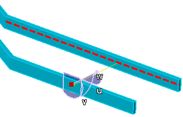
You will get the following behavior when you
select the option Match run extremity points during
offset connection creation (Tools - Options - Equipment & Systems -
Design Criteria) : After you do Steps 1 and 2 as
described above, the following happens:
- The slave segment becomes parallel to the master segment.
- The slave segment changes in length to match the master segment in
length.
- The compass displays.
- You can see a connector line between the
two segments when you click the Preview
button.

The difference in behavior with the option checked is that the two
segments become equal in length because the extremity points are
matched. You can now follow the procedures from Step 4 onward. |
|
 |