Generating an Integration Report
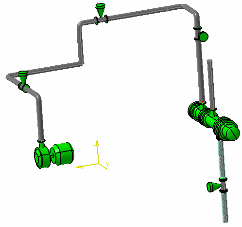
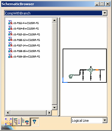
| This task shows you how to generate an integration report for a schematic driven design. | ||
|
|
If you are using a
customized project resource management file then you must insert a new
section available in the sample PRM file from Release 18. The section is
Design Validation, 2D3DIntegrationStatusReport Discipline Resources.
You need to insert this section in your PRM file or the Integration tool may
not work correctly. Adding this section allows the application to load all
the catalogs needed when processing objects from various disciplines. See also Integration Checks Explained. |
|
| 1. | Open your design documents - both
the schematic and the generated 3D design. This step is not required, because you can
select documents to be checked as explained in
Step 3. It is recommended, however.
|
|
| 2. | Click Analyze >
Functional-Physical Integration > Function Physical Integration Validation
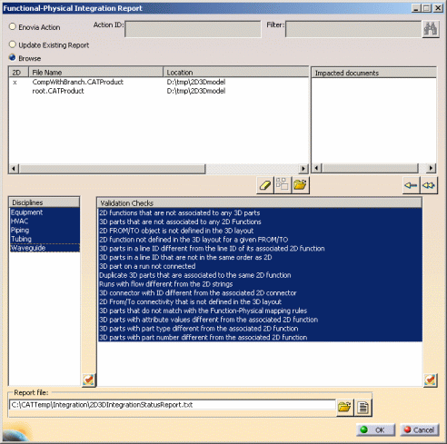
Report. The Functional-Physical Integration Report dialog
box opens. In the image below the user has made some selections.
|
|
| 3. | SELECTING FILE-BASED DOCUMENTS: Select the Browse option and click the button Select Documents to be Processed. Navigate to the directory where your design documents are located and select them. Both the schematic and the 3D document generated from it must be opened. The File Name and Location will display in the Functional-Physical Integration Report dialog box, as shown above. It is recommended that you identify the schematic by clicking next to it beneath the column 2D, as shown above. This makes the process of generating a report faster. If you want to remove a document then select it and click the Remove Selected Document from List button. NOTE: You should open the relevant 2D document, and the related 3D documents you want to check. You can also open the root, in which case all 3D documents beneath it will open. But do not take both actions - either open the root, or individual documents. For the following
three checks you need to open the root, because the connectivity information
is stored there. Note that after you select the root, the documents beneath
it will open. Do not select any of these 3D documents or two reports will be
generated. (The 2D document must be selected however, as described above.)
The checks are: 2D FROM/TO object is not defined in the 3D layout; 2D function not defined in the 3D layout for a given FROM/TO;
2D From/To connectivity that is not defined in the 3D layout.
SELECTING DOCUMENTS IN ENOVIA: If you want to filter the documents associated with the Action ID, by document name, then enter appropriate text in the Filter field. The filtered documents will display in the File Name field. If you want to search for impacted documents then select a document in the File Name field and click the Search for Impacted Documents button. Impacted documents will display in the pane. Impacted documents are explained elsewhere in this section. You can also move a document from the Impacted Documents pane to the File Name pane, select it, and search for impacted documents.
|
|
| 4. | In the Disciplines pane,
select the disciplines for which you want to check your document. In the
Validation Checks pane select the checks. You can
also click the "Select All" buttons to select all disciplines or checks. The OK button will not be available until you have selected at least one check, as well as all other relevant options. |
|
| 5. | The Report File
field displays the name and location of the file identified for the
resource 2D3DIntegrationStatusReport in the project resource
management file. If you want to select another output file then enter
the name and location or navigate to it using the Select
Output File button. The folders specified in the field
must exist for the report to be generated. Click the button Review Existing Reports to see the report you generated previously. Only the last report for the same report file is available. If you check the option Update Existing Report, and you have selected an output file, then the settings you selected when you last generated a report using that output file will be retained. This means you will not have to select documents in the File Name, Disciplines or Validation Checks field - the settings you selected the last time you generated a report will be used to generate the new report. |
|
| 6. | Click the OK button.
An
Error Report displays if there is an error, or you may see
the
Validation Summary Reports dialog box, showing the result of the design check. A portion of the
dialog box is shown below. Click on one of the validation checks to see
details of the check.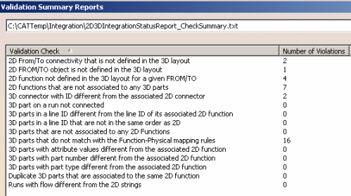 The reports generated are: the Check Summary Report and an Error Report if there are any errors. Click on the down arrow next to the report location field to select the reports. |
|
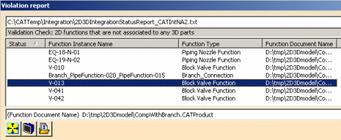
| 7. | Click on one of the checks to
display the Violation Report, which shows all the violations for that
check.
|
|
| 8. | You can perform the following
functions using the buttons available to you:
|
|
| 9. | You can enter a notation in the Status column, such as after fixing a violation. Click Save after you have made notations to save them in the report. | |
![]()
