|
3. |
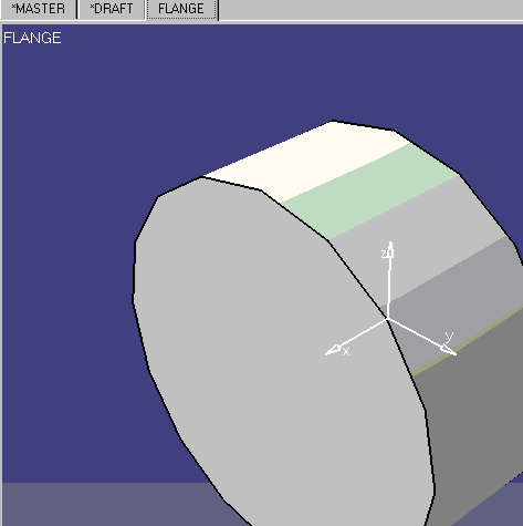
In V5, open the document you just migrated. The document will have
*Master and *Draft tabs, and tabs for each part in the model. Click on the
tab that has the name of the part you want to migrate to display the part.
|
|
4. |
With this part displayed, open a new V5 Tubing
Design document and then click Window - Tile, horizontal or vertical, as
you prefer. |
|
5. |
Select the project and discipline you want to
use by clicking Tools - Project Management. |
|
6. |
Click the Build Part button
 . The Create Part dialog
box displays. . The Create Part dialog
box displays. |
|
7. |
Click on the button next to the Component Type
field to display the Class browser. |
|
8. |
Expand the Tubing Part category and select a part type for
your part. It will display in the Component Type field. |
|
9. |
Enter a name for the part in the Symbol Name field. For
the sake of convenience, it is recommended that you use the same name the
part had in V4. Press Enter and then click Apply. The part will display in
the specifications tree. Do not click OK if you also want to create a
single representation. If the V4 part had both double and single
representations and you want to migrate the geometry of both, then you must
now create a single representation also, as shown below. |
|
10. |
After you click Apply (Step 7), the Manage
Representations button
 will become active in the Create Part box. Click this button to display the
Manage Graphic Representations dialog box.
will become active in the Create Part box. Click this button to display the
Manage Graphic Representations dialog box.
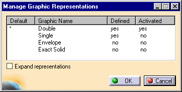
Click on "no" next to Single, and under the Defined column. It will
change to "yes", indicating that a single representation document has been
created. Check the Expand Representations checkbox so that both
representations are activated. Click OK. |
|
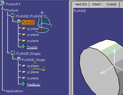
11. |
Both single and double representations will display in the
specifications tree, which should look like the image below.
|
|
12. |
Copy the geometry from your V4 part into this
application using standard Copy - Paste procedure. Select the V4 part
geometry, copy it, double click on the part name in the specifications tree
(starts Part Design) and paste what you copied on the entry Double. The
geometry is copied into Double, unless it is a solid. If the geometry is a
solid a new body is added. You must hide the three planes (xy, yz, zx).
Repeat this procedure for the single representation, pasting it on the
entry PartBody and hide the planes. Save the part and shape documents you
have just created. |
|
13. |
Connectors are not migrated. To add connectors
to the part see Creating and Modifying Connectors.
If you want to add connector specifications see
Associate
Specifications to a Connector. |
|
14. |
Properties are not migrated. To add values for
properties see Define Properties for a Part. |
 |
You must modify the
mapping table before these parts can be used in V5. See
Modifying the Mapping Table on how to do
this. |
|
15. |
Add the part to a catalog. See
Modifying a
Catalog to learn how to add parts. |
|
 |