A |
||||||||||||||||||
| authorized penetration |
An interference type that lets you define a margin within which two products can occupy the same space zone without generating a clash. Sag is taken into account. |
|||||||||||||||||
|
|
||||||||||||||||||
|
|
It is half the minimum thickness of the product. Maximum authorized penetration: The value entered for authorized penetration must not be greater than half the minimum thickness (t). |
|||||||||||||||||
|
Minimum authorized penetration: The value entered must not be less than twice the sag. |
||||||||||||||||||
|
|
Notes: This interference type:
|
|||||||||||||||||
B |
||||||||||||||||||
|
An option in the Distance and Band Analysis command that computes and visualizes the areas on products corresponding to a minimum distance within a user-defined range. |
||||||||||||||||||
|
2D Figure |
3D Figure |
|||||||||||||||||
|
|
||||||||||||||||||
|
The green area on A corresponds to all the points on A for which the minimum distance to B is within the user-defined minimum and maximum distance. The red area on A corresponds to all the points on A for which the minimum distance to B is less than the user-defined minimum distance. The points on A for which the minimum distance to B is within the user defined distance are calculated in 3D, and the result is the area inside the cone extending from B (see figure below) The result reflects the accuracy value (expressed in mm) specified in the Edit Distance and Band Analysis dialog box and not the exact maximum and minimum distance values defined by the user. To obtain a geometrical result approaching the exact minimum or maximum distance values, the accuracy value should be refined (be careful, the lower the accuracy value is, the longer the calculation time is and the higher is the memory consumption). Let's consider a = accuracy; then the green area = maximum distance +- a and the red area = minimum distance +- a |
||||||||||||||||||
|
A computation type whereby each product in the document is tested against all other products. |
||||||||||||||||||
|
A computation type whereby each product in the first selection is tested against all products in the second selection. |
||||||||||||||||||
C |
||||||||||||||||||
|
CGR stands for CATIA Graphical Representation. This format is the common format used for all V5 data. CGR files always have a .cgr extension. |
||||||||||||||||||
|
An interference type where a conflict is detected if two elements occupy the same space zone. |
||||||||||||||||||
|
An interference type where a conflict is detected if two elements are separated by less than a pre-defined distance. Also termed clearance violation or near miss. |
||||||||||||||||||
|
A visual comparison setting corresponding to the minimum distance between two products beyond which products are considered different. |
||||||||||||||||||
|
A last level entity in the product structure. |
||||||||||||||||||
|
A geometric comparison setting that determines the size of the cubes used to represent the material added and/or removed. |
||||||||||||||||||
|
An interference type where a conflict is detected if two elements are in contact. |
||||||||||||||||||
D |
||||||||||||||||||
|
A working mode in which the exact geometry is available and documents (V4 models, V5 CATParts, V5 CATProducts, etc.) are inserted as is. See also visualization mode. |
||||||||||||||||||
|
The second step when checking for interferences. The first step (initial computation) detects and identifies the different types of interference. Depending on your clash settings, the second step computes the graphics representation of interferences as well as the penetration depth or minimum distance. |
||||||||||||||||||
|
The direction along which a product must be moved in order to avoid a clash. Visualized as a vector. |
||||||||||||||||||
|
A geometric comparison setting that defines the fineness or coarseness of the display of the computation results. |
||||||||||||||||||
|
Options in the Distance and Band Analysis command that measure distances between products along x, y or z. |
||||||||||||||||||
|
|
||||||||||||||||||
|
Digital Mockup |
||||||||||||||||||
E |
||||||||||||||||||
|
A geometrical sub-set. |
||||||||||||||||||
G |
||||||||||||||||||
|
A set of products defined explicitly using the Group
|
||||||||||||||||||
I |
||||||||||||||||||
|
A computation type whereby, within any one selection, each product of the selection is tested against all other products in the same selection. |
||||||||||||||||||
|
A space conflict. Different types can be detected: clash, contact and clearance. See also authorized penetration. |
||||||||||||||||||
|
Interference checking and analysis is done on polyhedric models represented by triangular meshes. Results differ depending on the interference type selected for the analysis. The following illustrates expected results for the different analysis combinations. Contact + Clash |
||||||||||||||||||
|
|
If red zones overlap, a clash is detected. | If yellow zones only overlap, a contact is detected. | ||||||||||||||||
|
|
|
|||||||||||||||||
|
If the shortest distance (d) between the yellow zones is less than the total sag (sag1 + sag2), a contact is detected. |
||||||||||||||||||
|
|
Same illustration as left showing outer sag (green zone):
|
|||||||||||||||||
|
Legend for Contact + Clash illustrations:
|
||||||||||||||||||
|
Clearance + Contact + Clash
About Clearance Value: |
||||||||||||||||||
|
Penetration Depth |
||||||||||||||||||
|
Clash
|
Contact
|
|||||||||||||||||
|
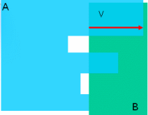
V is the penetration vector and visualizes the penetration depth. In the second illustration above, if you translate product A by V, both products are in contact. Important: If V < sag1 + sag2, a clash may be detected (see below). |
||||||||||||||||||
|
Clash
|
Contact
|
|||||||||||||||||
|
Penetration Depth versus Authorized Penetration The penetration depth (an interference result) is not to be confused with authorized penetration (an input). |
||||||||||||||||||
|
|
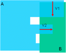
A clash is detected between products A and B. V is the penetration vector and visualizes the penetration depth. Note that V is greater than the authorized penetration in our illustration. If the authorized penetration is greater than distance d, no clash is detected. |
|||||||||||||||||
|
Line segments identifying clash conflicts between products. |
|
|||||||||||||||||
L |
||||||||||||||||||
|
The level of detail specifies at what level of detail the detailed computation is run. Two options are available: This mode is set on the DMU Clash - Detailed Computation tab of your settings (Tools > Options, Digital Mockup, DMU Space Analysis).
Element
|
||||||||||||||||||
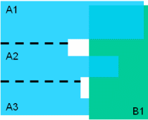 |
Level of detail = Element
(A1-B) = Clash |
Note: The Compute penetration depth or minimum distance
option is selected in During initial computation area
(This specific clash computation setting
is available in Tools > Options > DMU Space Analysis > DMU
Clash tab)
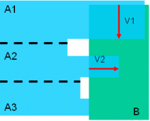 |
Level of detail = Element
|
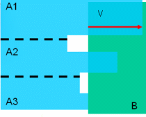 |
Level of detail = Element
|
Let's describe the various combinations of options and their impact on the result.
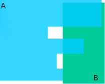 |
Level of detail = Product(A-B) = Clash Final Result: (A-B) = Clash |
 |
Level of detail = Product
|
 |
Level of detail = Product
|
Note that when Product is selected as level of detail, we can obtain a clash result with a value = 0
For example:
Specification Clash/Contact with Element or Product option selected
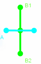 |
Level of Detail = ElementA is on the symmetry of sub-element of B and: (A-B1) = Contact Final Status = Contact Level of Detail = Product(A-B) = Clash Final Status = Clash |
An option in the Measure Between command that gives the approximate maximum distance normal to the selection. Two choices are available:
Maximum distance from 1 to 2: maximum distance of all
distances measured from selection 1.
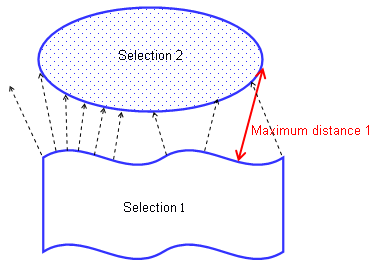
Maximum distance: the highest maximum distance between the maximum distance measured from selection 1 and the maximum distance measured from selection 2.
An option in the Distance and Band Analysis command that measures the distance between the two closest points of two product representations.
Also an option in the Measure Between command that measures the minimum distance, and if applicable the angle, between geometrical entities points, surfaces, edges, vertices and entire products).
For information on notations used for inertia.
The penetration mode determines how the penetration depth is computed. Two modes are available:
Element (default)
Product.
This mode is set on the DMU Clash - Penetration tab of your settings (Tools > Options, Digital Mockup, DMU Space Analysis).
Element Penetration Mode:
In this mode, penetration depth corresponds to the minimum distance by which it is necessary to translate an element to avoid a clash. The calculation is repeated for each pair of clashing elements and the maximum penetration depth output.
If you then translate the element, elements no longer clash but are in contact.
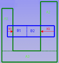
In our example, the green product (A) comprises three elements and the blue product (B) two elements.
Two different pairs of elements are clashing: A1 and B1; A2 and B2. The penetration depth for the first pair of elements is N1; for the second pair N2. The largest value is output, in our case, N2.
Note: You cannot use this calculation to translate products and avoid clashes.
Product Penetration Mode:
In this mode, penetration depth corresponds to the minimum distance by which it is necessary to translate a product to avoid a clash. If you then translate the product, products no longer clash but are in contact.
This mode corresponds to the penetration depth computation prior to Version 5 Release 8.
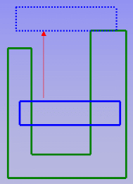
penetration vector
Visualizes the penetration depth. The origin of the
penetration vector is the center of inertia of the intersection curve.
Note that this vector may sometimes be located outside selected products.
Special case: when one product is completely included in another, the
origin of the penetration vector is the center of the local axis system of
one of the products.
In DMU workbenches, a subset or constituent part of a CATProduct document, for example a cgr file or V4 model.
Used in the Part to Part Clash, Clash,
Distance and Band Analysis, and Sectioning commands.
Corresponds to the fixed sag value for calculating tessellation on objects
(3D fixed accuracy) set in the Performances tab of Tools -> Options ->
General -> Display. By default, this value is set to 0.2 mm. Note
that results obtained differ depending on the sag value used.
In Visualization mode, you can dynamically change the sag value for
selected objects using the Tools > Modify SAG command.
A set of segments identifying the cross-sectional boundary produced by the intersection of a section plane and a selection of products. Sections are 2D views that help the user manage 3D documents.
The result of sectioning a product and cutting away the material from the cutting plane, beyond the slice or outside the box.
A cutting plane used to create sections and section cuts. The plane has limits and can be manipulated. This is the master plane when creating section slices and boxes.
A computation type whereby each product is tested against all other products in the document.
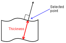
A measure mode that gives the approximate item thickness along the normal to the surface at the selected picking point.
Can be accessed from Measure Item and Measure Between commands.
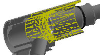
Graphics representation identifying products in contact (yellow) or separated by less than the specified clearance (green) distance.
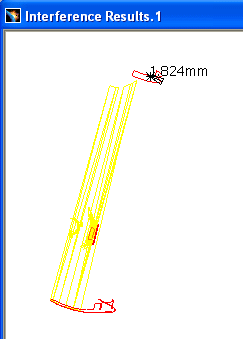
A working mode in which a representation of the geometry only is available and the corresponding cgr file, if it exists, is inserted from the data cache. See also design mode.
XML (Extensible Markup Language) is a standard format that can be used as a simple way to exchange data. The advantage of using this format to publish clash and distance results is two-fold:
Results and how the results are presented are two separate entities, so you can customize your own style sheet to present the results the way you want without impacting the results themselves.
XML makes documents smarter and more portable. You can for example publish the same results to a web browser as well as to your company database.
Note: XML processors letting you generate HTML pages corresponding to the XML file and style sheet are available on the market.