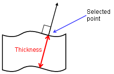
This task explains how to measure the thickness of a
selected item along the normal to the surface at the picking point.
Important: This measure is approximate. It is not associative and therefore
cannot be updated.
This command can be accessed from the Measure Item and Measure Between commands.
Insert the following sample model files: ATOMIZER.model, BODY1.model, BODY2.model, LOCK.model, NOZZLE1.model, NOZZLE2.model, REGULATION_COMMAND.model, REGULATOR.model, TRIGGER.model and VALVE.model.
They are to be found in the online documentation file tree
in the common functionalities samples folder cfysm/samples.
-
Switch to Design Mode (Edit > Representations > Design Mode).
-
Set View > Render Style to Shading with Edges.

Note: You cannot use this command, if Shading only is selected.
-
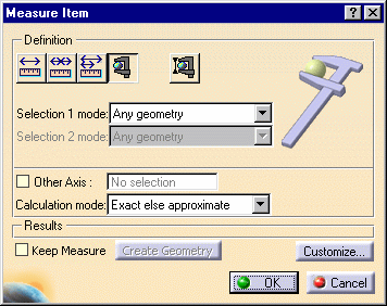
Click the Measure Item icon
 .The
Measure Item dialog box appears.

-
For more information on measuring other properties of selected items (points, edges, surfaces and entire products), see Measuring Properties.
-
The Keep Measure option lets you keep current and subsequent measures as features.
-
-
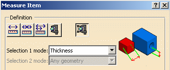
Click the Thickness icon
 in the
dialog box or set the measure mode in the Selection 1 mode drop down list
box to Thickness.
-
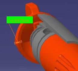
Make your measure.
Notes:
-
A dynamic feedback exits as you move your cursor over the item.
-
Thickness is measured along the normal to the surface at the picking point. An approximate value is given.


-
-
Click OK when done.
If you selected the Keep Measure check box in the dialog box, your measure is kept as a feature.

This measure is not associative and therefore cannot be updated. This is identified in the specification tree by the measure icon plus a lock.


The Properties command (Graphics tab) lets you change the fill color and transparency as well as the color, line type and thickness of measure lines.
Note: You cannot vary transparency properties, the current object is either the selected color or transparent
![]()