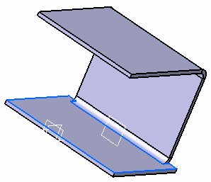
In our example, we chose local fold and unfold of bends.
Unfolding
Click Unfolding
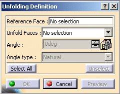
. The Unfolding Definition dialog box is displayed.
The following options are available:
Reference face: fixed part of the body.
Unfold Faces: bend(s) to unfold.
Angle: disabled, corresponds to the angle of the selected face to fold that is 90 degrees by default.
Angle type: disabled, set to natural by default.
Select Wall.1 as reference face in the geometry area.
Angle type is disabled and set to Natural. Angle is at 90 degrees.
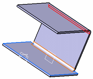
Select Cylindrical Bend.1 and Cylindrical Bend.2 as Unfold faces in the geometry area.
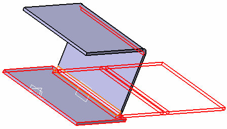
Click Preview to visualize the unfolding of the bends you selected.
Click the Select all option if you want to unfold all the bending faces of the part.
Click OK to unfold the bends.
The Unfolding.1 feature is created in the specification tree.
You can unfold non canonical faces such as a curved flange.
Folding
-
Click Folding
 .
The Folding Definition dialog box is displayed.
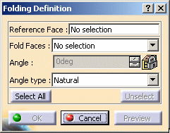
The following options are available:
-
Reference face: fixed part of the body.
-
Fold faces: bend(s) to fold.
-
Angle: corresponds to the angle of the selected face to unfold.
-
Angle type:
-
Natural: when selected, the angle is set to the initial bend value by default (90 degrees in our example) and is disabled.
-
Defined: allows you to choose the bend angle with the up and down arrows.
-
Spring back: the angle of the bend is based on the natural angle with additional degrees.
-
-
-
Select Wall.3 as reference face on the geometry.

-
Select Cylindrical Bend.1 on the geometry.
A red arrow is displayed indicating the direction of the angle. 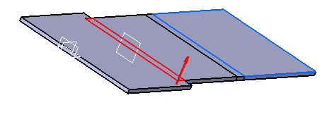

Click the Select all option if you want to unfold all the bending faces of the part.
-
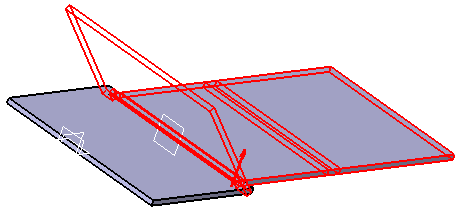
In the Folding Definition dialog box, select Defined as angle type and 45 degrees as angle.
-
Click Preview to visualize the folding of the bend you selected.
-
Click OK to fold the selected bend.
The Folding.1 feature is created in the specification tree. 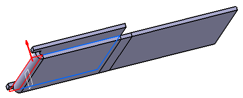
Bend folded with a Spring back angle at 90 degrees 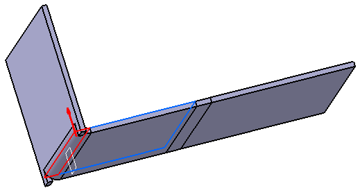
Bend folded with a natural angle at 90 degrees 
To fold or unfold a part with a bending cycle, each element of the cylindrical bend has to be selected individually. 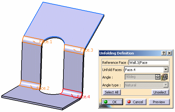
-
Multiselection is possible but since unfold faces must be in the same domain you must fold/unfold the parts one after the other. You cannot create folded faces with null radius.
-
The fold/unfold feature is only available in folded view, as the flattened view is not modified.

- You cannot fold/unfold bends:
- if faces to fold are not in the same domain,
- if cylindrical faces are generated from stamps or rolled walls.
- You cannot fold back an unfolded bend if its radius is null.

In hybrid context, even though a wall is created with one or several features, none are aggregated under the wall in the specification tree. 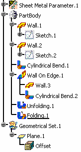
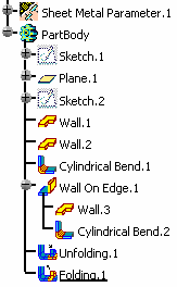
Specification tree's behavior in pre-hybrid context Specification tree's behavior in hybrid context Yet, if you open a part created in a previous release, the specification tree will be displayed accordingly to the previous behavior.
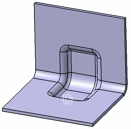
For more information about Hybrid Design, refer to the Hybrid Design section.It is possible to fold/unfold a part with a stamp located on or inside a bend. To do so, select the bend. 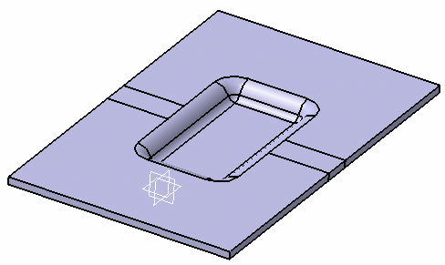
-
![]()
