The fillet surface is obtained by rolling a sphere, which radius would vary, over the selected edge.
Open the FilletVariableRadius1.CATPart document.
-
Click Variable Fillet
 .
.The Variable Radius Fillet Definition dialog box appears. 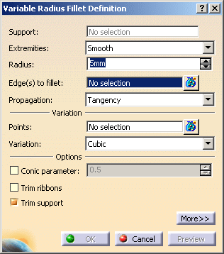
-
Select the edge to be filleted and click Preview.
The system detects the two vertices and displays the default radius value. 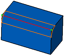
-
Use the combo to select the desired type of extremity for the fillet:
-
Straight: no tangency constraint is imposed at the connecting point between the fillet and the initial support, generating sometimes a sharp angle.
-
Smooth: a tangency constraint is imposed at the connection between the fillet surface and the support surfaces, thus smoothing the connection
-
Maximum: the fillet surface is limited by the longest selected edge
-
Minimum: the fillet surface is limited by the shortest selected edge
(Refer to Shape Fillets) -
-
You can also choose the propagation type:
-
Tangency: the fillet is propagated up to the first edge that is not continuous in tangency.
-
Minimal: the fillet is propagated up to the first geometric limitation.
-
-
To add an additional point on the edge to make the variable radius fillet, click the Points field and select a point on the edge.
-
Enter a new Radius value for this point.
-
Set the Variation mode to Cubic to obtain a smooth transition from one radius to another.
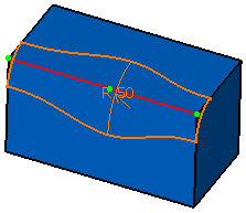
-
Select the Conic parameter check box. This check box allows you to vary the section of the fillet.

For parameter comprised between or equal to: - 0.5, the resulting curve is a parabola.
- 0 < parameter < 0.5, the resulting curve is an arc of an ellipse
- 0.5 < parameter < 1, the resulting curve is a hyperbola.

- Conical fillets do not handle twist configurations. If a twist is detected, the fillet operation fails.
- Conical fillets may produce internal sharp edges. However, healing is used to smooth these sharp edges. Refer to Healing Geometry for more information.
- If the fillet surface curvature is lower than the support curvature, fillet surface relimitation may fail. In such cases, the conic parameter has to be decreased.
-
You can check Trim support to relimit the support elements and assemble them to the fillet.
-
Click OK to confirm the operation.
The surface (identified as EdgeFillet.xxx) is added to the specification tree. 
This is the fillet you would obtain using the Linear variation mode. In this case there is a straight transition from one radius to another. 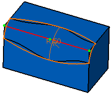

Note that the selection of the feature prevails over the selection of the sub-element.
To select a sub-element, you need to apply the ''Geometrical Element'' filter in the User Selection Filter toolbar.
For further information, refer to Selecting Using A Filter in CATIA Infrastructure User's Guide.
Limiting Fillets
-
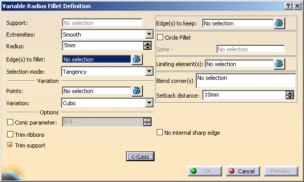
Once the edge to be filleted has been selected, and the radius keyed in, click Preview then More>>.
-
Click in the Limiting element(s) field, then select the trimming element(s). Here we chose Extrude.7.
These elements can either be surfaces, planes, or points on edges. 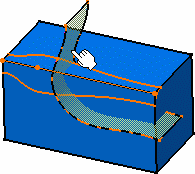
An arrow indicates which portion of the fillet is to be retained. If needed, you can click on this arrow to inverse it, to retain the opposite side of the fillet. 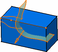

- It is possible to use one or more limiting elements.
- You can define a limiting element just by clicking a point on one of the selected edges to be filleted.
-
Click OK to create the limited fillet.
In the illustration, the limiting surface has been hidden. 
-
You can create limiting elements just by clicking on the edge to be filleted.
The application displays this element as a blue disk. 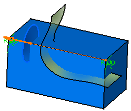
-
You can select points as limiting elements. These points must be located on the edge to be filleted and they must have been created using On Curve available in the Point Definition dialog box.
-
You can define variable radius fillets on closed edges.
However, the application defines a default vertex on closed edges when applying this command. To define the fillet, you need to remove this vertex first of all, then use 3D points only. 
Note that the Linear variation mode is not valid for closed edges or closed sets of edges that are continuous in tangency. In these cases, the Cubic mode is automatically applied. -
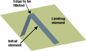
Make sure the limiting element is not larger than the initial element, as illustrated here. If so, decrease the size of the limiting element as prompted by the warning message.

If the Conic parameter check box is selected, the Edge(s) to keep field and the No internal sharp edge option are grayed out. Conversely, if the Edge(s) to keep field or the No internal sharp edge option is selected, the Conic parameter check box is disabled. -
Trimming Overlapping Fillets
- In some cases, fillets may be overlapping. Trim ribbons lets you solve this by trimming the fillets where they overlapping. For further information on this option, refer to Trimming Overlapping Fillets.
- Make sure the support involved does not present any sharp edge,
because the fillet would be relimited, and may yield unexpected results,
or could not be computed. For example, in the illustration, the fillet
cannot be propagated along the whole edge because the fillet is stopped
onto the vertical edge.
In this case, you should try to remove this discontinuity by either filleting the sharp edge or modifying the support surfaces. 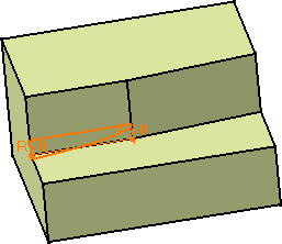
Minimizing Internal Sharp Edges
Filleting Volumes
![]()
-
Click Variable Fillet
 .
.The Variable Radius Fillet Definition dialog box appears. -
Select the edge to be filleted.
-
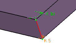
Set the first Radius to 10mm and the second Radius to 5mm.
-
Click OK to create the fillet volume.
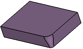

Trim support is grayed out. It cannot be used with volumes.
![]()