 |
This task shows how to create swept surfaces that use
an implicit circular profile. |
| |
The following subtypes are available:
|
 |
Open the
Sweep1.CATPart document. |
| |
|
| |
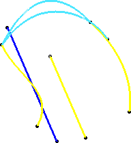
Three guides
|

|
-
Click Sweep
 . .
| The Swept Surface Definition dialog box appears. |
-
Click the Circle icon and select Three
Guides from the Subtype drop-down list.
-
Select three guide curves.
-
If needed, select a Spine to specify a spine
different from the first guide curve or center curve.
If a plane normal to the spine intersects one of the guiding curves at
more than one points, the application chooses the closest point to the spine
point.
-
Click OK to create the swept surface.
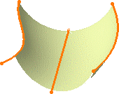
| The surface (identified as Sweep.xxx) is added to the
specification tree. |
 |
|
| |
Two guides and radius
|

|
-
Click Sweep
 . .
| The Swept Surface Definition dialog box appears. |
-
Click the Circle icon and select Two
guides and radius from the Subtype drop-down list.
-
Select two guide curves and type a Radius
value.
| You can then choose between six
possible solutions (among them, two new complete circular
solutions) by clicking the Previous or Next
button or entering a solution number in the Solution(s)
field. |
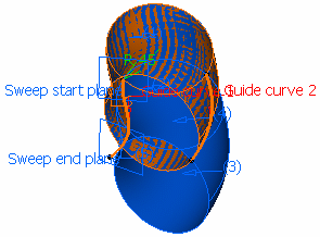 |
| Choosing a circular solution (radius=45) |
-
If needed, select a Spine to specify a spine
different from the first guide curve or center curve.
If the plane normal to the spine intersects one of the guiding curves at
different points, it is advised to use the closest point to the spine
point for coupling.
-
Click OK to create the swept surface.
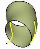
| The surface (identified as Sweep.xxx) is added to the
specification tree. |
 |
|
| |
Center and two angles
|

|
-
Click Sweep
 . .
| The Swept Surface Definition dialog box appears. |
-
Click the Circle icon and select Center
and two angles from the Subtype drop-down list.
-
Select a Center Curve and a Reference
angle curve.
| You can relimit the swept surface by entering two angle values. |
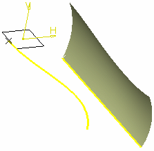 |
In the above example, we selected the following values:
Center curve: DemoGuide 1
Reference angle: DemoGuide 3
Angle 1: 50 deg
Angle 2: 0 deg |
-
If needed, select a Spine to specify a spine
different from the first guide curve or center curve.
If the plane normal to the spine intersects one of the guiding curves at
different points, it is advised to use the closest point to the spine
point for coupling.
-
Click OK to create the swept surface.
| The surface (identified as Sweep.xxx) is added to the
specification tree. |
|
| |
Center and radius
|

|
-
Click Sweep  . .
| The Swept Surface Definition dialog box appears. |
-
Click the Circle icon and select Center
and radius from the Subtype drop-down list.
-
Select a Center Curve and type a Radius
value.
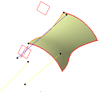 |
In the following example, we selected the following values:
Center curve: DemoGuide 3
Radius=20mm |
-
If needed, select a Spine to specify a spine
different from the first guide curve or center curve.
If the plane normal to the spine intersects one of the guiding curves at
different points, it is advised to use the closest point to the spine
point for coupling.
-
Click OK to create the swept surface.
| The surface (identified as Sweep.xxx) is added to the
specification tree. |
|
| |
Two guides and tangency surface
|

|
-
Click Sweep  . .
| The Swept Surface Definition dialog box appears. |
-
Click the Circle icon and select Two
guides and tangency surface from the Subtype drop-down list.
-
Select two guide curves, and a reference surface to which
the sweep is to be tangent.
-
Depending on the geometry, there may be one or two
solutions from which to choose. The solution displayed in red shows
the active sweep.
-
If needed, select a Spine to specify a spine
different from the first guide curve or center curve.
If the plane normal to the spine intersects one of the guiding curves at
different points, it is advised to use the closest point to the spine
point for coupling.
-
Click OK to create the swept surface.
| The surface (identified as Sweep.xxx) is added to the
specification tree. |
 |
|
| |
One guide and tangency surface
|

|
-
Click Sweep  . .
| The Swept Surface Definition dialog box appears. |
-
Click the Circle icon and select One
guide and tangency surface from the Subtype drop-down list.
-
Select a guide curves, a reference surface to which the
sweep is to be tangent, and type a radius value.
-
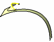
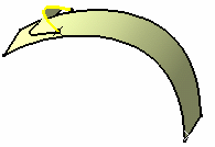
Check Trim with
tangency surface to perform a trim between the swept surface and
the tangency surface. The part of the tangency surface that is kept is
chosen so that the final result is tangent.
 |
|
 |
| With Trim option checked |
|
With Trim option unchecked |
-
If needed, select a Spine to specify a spine
different from the first guide curve or center curve.
If the plane normal to the spine intersects one of the guiding curves at
different points, it is advised to use the closest point to the spine
point for coupling.
-
Click OK to create the swept surface.
| The surface (identified as Sweep.xxx) is added to the
specification tree. |
|
|
|
Limit curve and tangency surface
|

|
-
Click Sweep  . .
| The Swept Surface Definition dialog box appears. |
-
Click the Circle icon and select
Limit curve and tangency surface from the Subtype drop-down list.
-
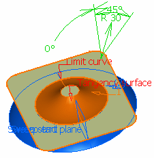
Select a limit curve and a reference surface to which the
sweep is to be tangent, and type a radius value.
| You can relimit the swept surface by entering two angle values. |
 |
 |
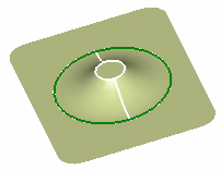
- The limit curve must lie on the input surface.
- Angles are measured from the tangent plane.
|
-
If needed, select a Spine to specify a
spine different from the limit curve.
-
Click OK to create the swept surface.
| The surface (identified as Sweep.xxx) is added to the
specification tree. |
 |
|
| |
Optional Elements
|
| |
Refer to Creating Swept
Surfaces. |
|

|
![]()