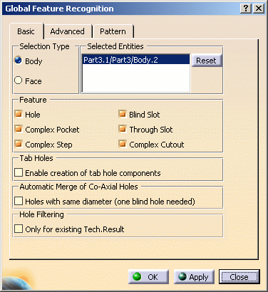
- To create axial machining features only, just select the Hole checkbox.
- To create prismatic machining areas only, select all the checkboxes except the Hole checkbox.
- To create all
holes included in a tab hole, select the Enable creation of tab hole
components checkbox.
A tab (or tabulated) hole is more complex than a Part Design hole in that its hole chain (that is, all faces) do not match a Part Design feature.
If the checkbox is not selected, the holes belonging to the tab holes are not created (default behaviour).
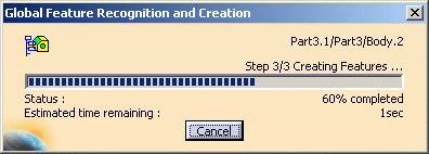
All recognized machinable features are added to the Manufacturing View.
However, suppose a pocket has a child pocket and the top face of upper pocket is selected.
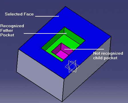
The child pocket will not be created as it does not open directly onto the selected face.
Graphic and Text Feedback about Machinable Features
When you select or move the mouse over a Machinable Axial Feature in the Manufacturing View, feedback in 3D Viewer shows:
- Highlight of flank RSURs referenced by the Machinable Axial Feature
- The entry point and entry vector of the feature.

Machining direction of a recognized "through feature" can be reversed by right clicking that feature in Manufacturing View and selecting the Reverse Machining Direction contextual command.
This command is not available for the blind features, as they can be machined in only one direction. Also this command cannot be accessed if the feature is machined.
The identifier of the Machinable Axial Feature is shown as follows:
Machinable Axial Feature.1 (Simple Hole Diameter=12mm Depth=20mm)
representing in a summary the parameters of the feature.
If you rename the feature:MyFeature.1 (Simple Hole Diameter=12mm Depth=20mm)
Both the graphical representation and the feature in the Manufacturing View are associative and always up-to-date, positioned and filled according to design changes. When geometry can no longer be retrieved from a feature (referenced RSURs are no longer in Design Part, for example) no user representation is displayed.
Advanced Parameters
The Advanced tab of the Global Feature Recognition dialog box contains a number of parameters for specific processing.
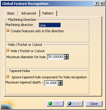
Machining Direction
You can specify a machining direction by selecting a face, a line or an edge. Created features will then have a machining axis parallel to the selected direction.
By specifying a machining direction, you can choose to create features that open in that direction only. For example, this may correspond to the machining direction of a particular machine setup.
If no machining direction is selected, the Create features only in this direction checkbox cannot be selected.
Hole / Pocket or Cutout
Depending on the value assigned for the maximum hole diameter, you can choose to create:
- either holes
- or circular pockets or cutouts.
Using this capability:
- large diameter holes can be created as Pockets
- small diameter intersecting holes can be created as Holes instead of a single complex pocket.
Make sure you have selected the appropriate Feature type in the Basic tab (for example, if you want to recognize a hole as a pocket, select the Hole and Complex Pocket checkboxes or just the Complex Pocket checkbox).
The behavior can be illustrated by means of the following example.
Consider a selected face with 4 holes with 10mm diameter and 4 holes with 20mm diameter.
Case A
Basic tab: Complex Pocket to be recognized
Advanced tab: check box selected and maximum diameter for hole set to 15mm.
Result: 4 holes of 20mm diameter will be recognized as Complex Pockets; 4
holes of 15mm diameter will not be recognized.
Case B
Basic tab: Hole to be recognized
Advanced tab: check box selected and maximum diameter for hole set to 15mm.
Result: 4 holes will be recognized as Holes of diameter 20mm; 4 holes will
be recognized as Holes of diameter 10mm
Case C
Basic tab: Complex Pocket to be recognized
Advanced tab: check box not selected, so no maximum diameter is set for
hole.
Result: All the holes will be recognized as Complex Pockets.
Basic tab: Hole to be recognized
Advanced tab: check box not selected, so no maximum diameter is set for
hole.
Result: All the holes will be recognized as Holes.
Ignore Tapered Hole Component
You can choose to ignore the fact that the hole type is tapered during feature recognition. In this way, you can force chamfered holes to be recognized as simple holes.
Chamfered hole:

Recognized hole:

Selection of Bodies
One or more Bodies can be selected.
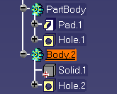
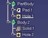
For feature recognition, the In-Work object must be either a Body or the last component of a Body. For example, in the figures below:
- if you want to use Body.2 for feature recognition, the In-Work object must be either Body.2 or Hole.2.
- Body.2 and Hole.1 are valid In-Work objects.
Interrupt Behaviour
Three types of message appear on progress bar depending on the step in which the recognition process is running:
- Preprocessing: in this step pre-processing is done for recognizing features.
- Recognizing Features: In this step actual feature recognition happens.
- Creating Features: In this step recognized features are created in the manufacturing view, analysis parameters are computed, and patterns are created for recognized holes if pattern creation options are selected.
The behaviour when you click the Cancel button to interrupt the process depends on the step in progress:
Pre-processing:
If you cancel the process during pre-processing
before the actual feature recognition, there will not be any recognized
features.
In this case no feature will be created and the progress bar is no longer
displayed.
Recognizing Features:
If one or more features are recognized at the time of interruption, a
message box appears asking if you want to create these recognized features
(Yes/No):
- Yes: The features recognized up until that point would be
created. During this creation, the progress bar will be displayed.
After creation, the progress bar will disappear and the Global Recognition summary panel will be displayed. It will show the actual number of features created. - No: No feature and pattern will be created and the
progress bar will disappear.
Also, the Global Recognition summary panel will not be displayed.
Creating Features:
A message indicates that the Creation step was
interrupted.
Then the Global Recognition summary panel is displayed, showing the actual
number of features created up until that point.
Pattern Creation behavior:
Patterns are not created if the process is interrupted (at any step), even
if the pattern creation options are selected.
Support of Technological Results
In the Part Design workbench, the Create Technological Results contextual command on a part body creates a Technological Results node containing technological information in the specification tree.
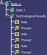
This technological information (thread, minimum and maximum tolerances) can be retrieved when creating axial features and machining patterns.
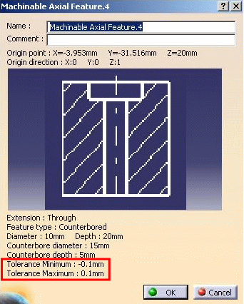
When Technological Results exist on the body selected for feature recognition, technological information (thread, minimum and maximum tolerances) are retrieved in both Local and Global Feature recognition. Created axial machinable features then include the corresponding technological information:
- Thread semantic value (M8, for example)
- Minimum and maximum tolerance values.
Information can be retrieved only when Multi-Model Link (MML) documents are loaded. This allows creating machining features using propagated Technological Results attached to multi-model geometry without needing to load the original documents.
This capability also allows creating axial machining features on propagated Technological Results attached to transformed (translated, rotated, mirrored, patterned, and so on) Part Design Hole and Thread features.
If no Technological Results exist, technological information (thread, tolerances) is retrieved from the design hole.
Automatic pattern creation groups axial machinable features using technological criteria (thread, tolerance). Technological information set on the machining axial feature is used to create the pattern.
Technological Results capability does not take into account semantic
tolerances (H7, for example). Any semantic tolerances are retrieved from
design holes even if Technological Results have been generated.
If no Technological Results have been created on the body, technological
information is retrieved from design holes.
![]()