| Positive offset | Negative offset | |
| To |
 |
 |
| Past |
 |
 |
The information in this section will help you create and edit Sequential Turning operations in your manufacturing program.
You can create a sequence of basic Go, Go InDirv, Go Delta, and Follow tool motions in a single Sequential Turning operation. PP words can be inserted in the sequence of tool motions.
When you select the Tool motion management icon a panel is displayed listing any previously created tool motions and PP words. You can create or edit tool motions and PP words.
If there are no previously created tool motions listed in the Sequential Turning dialog box, the first one must be a Go Standard motion to a point. It specifies either the absolute start position from where the following position can be computed or the end point of the approach macro (if the operation has one).
When defining a tool motion, the corresponding new tool position is displayed according to all the options that were selected for creating this motion.
The following topics are dealt with in the paragraphs below:
All tool types with compatible inserts are authorized.
Refer to Trigon Insert Used on a Groove
Insert-holder for more information about this tooling configuration.
You can select lines, curves and edge elements as check and drive elements. Points can also be selected as checks. Selected elements must be located in the plane defined by the machine spindle axis and radial axis.
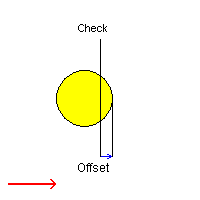
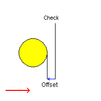
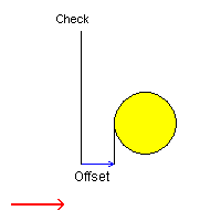
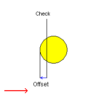
The following table summarizes how the tool is positioned with respect to a check element depending on the TO/PAST modes and negative/positive offset values.
| Positive offset | Negative offset | |
| To |
 |
 |
| Past |
 |
 |
In Go motion, the program positions the tool with respect to one or two check elements.
When only one check element is selected, the tool is projected onto the check element.
When two check elements are selected, the tool is positioned with respect to the two check elements.
The tool is positioned with respect to each check element depending on the TO-ON-PAST mode.
TO: the tool nose is positioned tangent to the near side of the selected
element with a possible offset.
ON: the tool nose is positioned on the selected element, with a possible
axial or radial offset (normal offset, collision avoidance and safety angles
are not applicable).
PAST: the tool nose is positioned tangent to the far side of the selected
element with a possible offset.
The first check element can be point, line, curve, or edge type elements.
If it is a point, no second check element can be selected. Otherwise, the second
check element can be line, curve or edge type elements.
Note that for the first Go Motion of an operation, the user can define a chosen direction of motion by means of a Reference point. This reference point will be used in determining the exact Tool Position considering the Check modes, offsets, and so on. See Reference Point for more information about this option.
The following options are available when defining a Go motion:
Note that the positioning mode (TO, ON, PAST) and offsets are not applicable when the tool is positioned on a point.
In Go InDirv (Go in Direction Vector) motion, the tool moves in a given direction
up to the selected check curve.
The tool is positioned with respect to the selected element depending on the
TO-ON-PAST mode.
TO: the tool nose is positioned tangent to the near side of the selected
element with a possible offset.
ON: the tool nose is positioned on the selected element, with a possible
axial or radial offset (normal offset, collision avoidance and safety angles
are not applicable).
PAST: the tool nose is positioned tangent to the far side of the selected
element with a possible offset.
The selected check curve can be edge, line and curve type elements.
The following options are available when defining a Go InDirv motion:
In Go Delta motion, the tool move is based on the current position of the tool. The TO-ON-PAST mode is not proposed.
The following options are available when defining a Go Delta motion:
In Follow motion, the tool follows a drive element up to a check element. The check element is to be selected in the Follow motion and can be an edge, line, a curve or a point.
The drive element is a curve on which the tool is positioned by a preceding motion. Therefore, the preceding motion must be a Go, Go InDirv or Follow motion. A Go to a point or a Go Delta cannot precede a Follow motion.
If the preceding motion is a Go motion, the first selected check curve is used as drive curve for the Follow motion.
If the preceding motion is a Go InDirv motion, the selected check curve is used as drive curve for the Follow motion.
If the preceding motion is a Follow motion, the check element of the preceding Follow motion is used as drive curve when this check element is not a point and the Change Drive option of the preceding Follow motion is set. Otherwise, both consecutive Follow motions share the same drive curve.
Note that:
The tool will follow the drive element up to the check element. The final
tool position will be determined by the TO-ON-PAST mode:
TO: tool nose tangent to the drive element and before the check element
with a possible offset.
ON: tool nose tangent to the drive element and on the check element,
with a possible axial or radial offset (normal offset is not applicable).
PAST: tool nose tangent to the drive element and after the check element
with a possible offset.
The following options are available when defining a Follow motion:
When check limit mode is set to Extended, a virtual tangent element is added
to each extremity of the check element before it is actually taken into account
as a check element.
Therefore, if there is no intersection between the drive and check elements,
the final tool position may be located at the intersection of the drive curve
and a tangent of the check element.
When check limit mode is set to Actual, no virtual tangent element is added.
Therefore, the final tool position is located on the check element.
Furthermore, please note that control over geometric extrapolation is not controlled in the Follow motion but on the preceding motion that positions the tool on the drive element.
Note that collision avoidance is taken into account for positioning in ON mode, and that left and right safety angles are only considered in collision avoidance mode.
The tool positioning for the first motion of a Sequential Turning Operation with respect to TO/ON/PAST is specified according to a Reference Point. This point can be derived from the previous operation or can be selected using the Reference Point symbol in the dialog box.
Note that Reference Point definition is optional. If a Reference Point is not defined, the tool is positioned by default with respect to the check elements depending on the TO-ON-PAST setting.
Click the point symbol in the dialog box then select the desired point or right-click the symbol to display contextual commands.
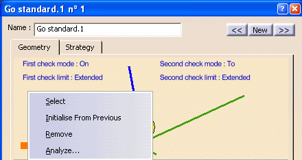
Select: Pick a point as a reference from the 3D window.
Initialise from Previous: Automatically take a Reference point
which has been initialised from the previous Machining Operation or Tool Change.
If the current Sequential Turning operation immediately follows a Tool Change,
then Initialise from Previous will take the Tool Change point as
Reference Point. Otherwise it will be the last point of the previous machining
operation (which is the end point of the retract motion, if a retract motion
is present on the previous operation).
Analyze: Visualise the Reference Point in the 3D window.
Remove: Reject the previous selection and make a new selection.
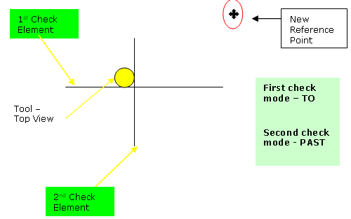
To illustrate Reference Point behavior, the two figures below have identical check modes on both check elements. The only difference is the position of the Reference Point. Notice how a change in Reference Point affects the Tool Position.
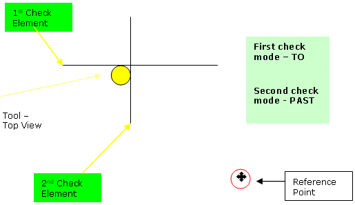
With a new Reference Point position :
then you can give a Machining Speed value.
The following feedrates can be set to either Angular units (length per revolution) or Linear units (length per minute):
In addition to these global feedrates, local feedrates can be applied to each tool motion.
The following Approach and Retract macros are proposed: Direct, Axial-radial,
Radial-axial, and Build by user.
The selected macro type (Approach or Retract) defines the tool motion before
or after machining.
Various feedrates are available for the approach and retract motions (RAPID, lead-in, lift-off, and so on). Local feedrates can be set to either Angular units (length per revolution) or Linear units (length per minute).
See Define Macros on a Turning Operation for more information.