![]()
This task shows how to create Point Surface joints in a V5 mechanism.
![]()
Open the
Create_CVjoint.CATProduct document.
![]()
When you create joints, you can define the mechanism within the same dialog box. Remember though, that you create a mechanism independently from the joints by selecting Insert > New Mechanism... from the menu bar.
-
Click the arrow within the Revolute Joint icon from the DMU Kinematics toolbar (Revolute joint is the default joint type)
-
Undock the Kinematics Joints toolbar:

-
Select CV Joint
 .
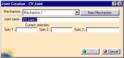
The Joint Creation: CV Joint dialog box is displayed.
-
Click New Mechanism. The Mechanism Creation dialog box is displayed:

In our example, keep the default name Mechanism.1.
-
Select Spin 1 either in the geometry area or in the specification tree. In our example, select the blue cylinder axis as shown below:

The current selection field is automatically updated.
-
Select Spin 2, for example the green cylinder axis:

-
Select Spin 3, the yellow cylinder axis.

-
Click Ok to end the CV joint creation.

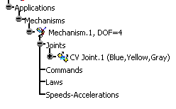
The tree is updated:

Note, you need to add a fixed part and to create revolute joints (with at least one command) to simulate this mechanism.
-
Open the CVjoint_Result.CATProduct document to check your result and simulate the mechanism
(double-click mechanism.1 to display the Simulation with command dialog box).
![]()
For more information, refer to About Joints and Creating Mechanisms and Joints.
![]()