 |
This task shows you how to import into a CATPart document
the data contained in an IGES file. Once imported, the data can be handled
just as if it were created as a CATPart.
The main purpose of such an import is to be able to create shells from IGES
faces but you may also find it
useful for re-using face contours in the Sketcher application, deforming
NURBs in Generative Shape Design or
using faces in other V5 applications. |
|
The table entitled What about
the elements you import ? provides information on the entities you can
import.
You can find further information in the Advanced Tasks:
and in the Customizing
3D
IGES Settings chapter.
Statistics about each import operation can be found in the
report file created. |

|
The function "Insert / Existing Component" for IGES files is provided by
the MULTICAx IGES plug-in
and requires a MultiCad license. |
 |
-
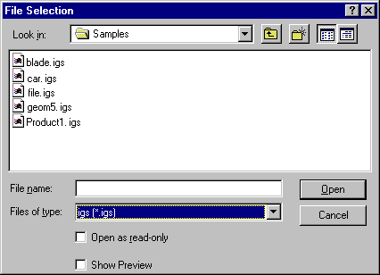
Select the File > Open command.
The File Selection dialog box is displayed.
-
If the directory contains many different types of files
you may wish to set the .igs extension in the Files of type field.
This displays all files with the extension "igs" contained in the selected
directory.
|
 |
- In V5, both files with the extension
"igs" and IGS can be imported to a
CATPart document.
- Whereas the path of an IGES file to import may contain non-ASCII characters, the
name of the file itself must contain only ASCII characters.
|
| |
-
Select the .igs file of your choice and click Open.
| A progress bar is displayed. |
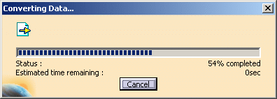 |
| You can use the Cancel button to interrupt the transfer
at any time. |
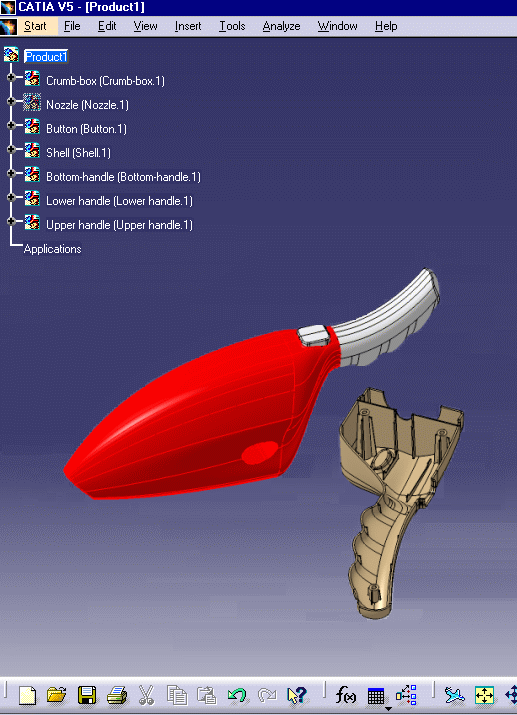
This creates a new document similar to a CATPart document in all
respects and containing all surfaces
and 3D wireframe geometry. The data is now available in your session. |
 |
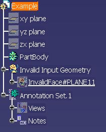
- Some invalid geometries may be detected.
- The reference planes are hidden at import.
|
|
|
Several 3D IGES import options can be customized:
|
|
 |
|
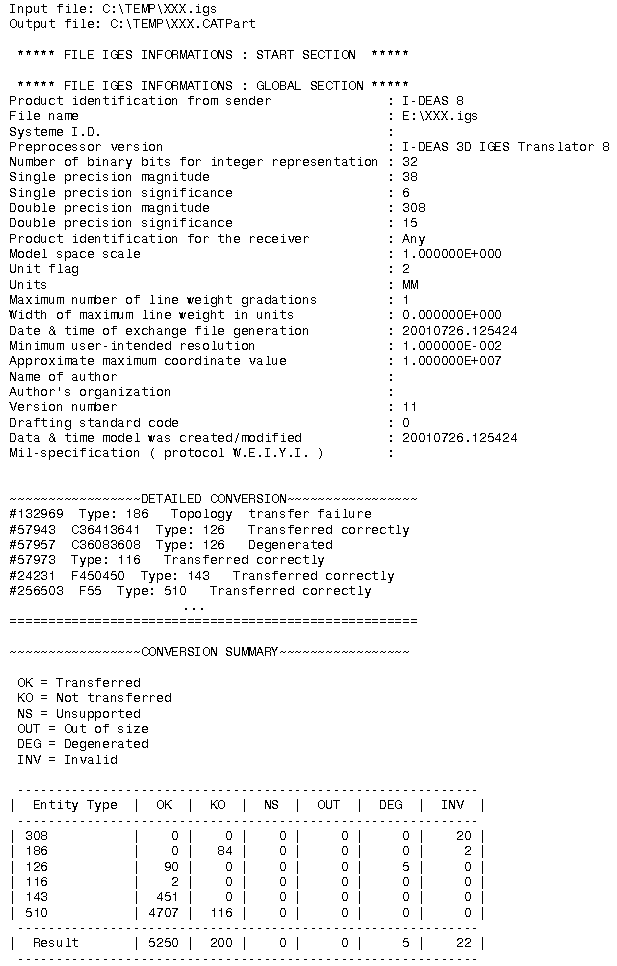
After the recovery of 3D IGES files, V5 generates:
-
a report file (name_of_file.rpt) where you can
find references about the quality of the transfer
-
and an error file (name_of_file.err) .
These files are created in a location referenced by
-
the USERPROFILE variable on NT. Its default
value is
Profiles\\user\\Local
Settings\\Application
\Data\\Dassault
Systemes\\CATReport
on NT (user being you logon id)
-
the HOME variable on UNIX. Its default value is
$HOME/CATReport on UNIX.
|
 |
Always check the report and error files after a conversion
!
Some problems may have occurred without been visually highlighted. |
|
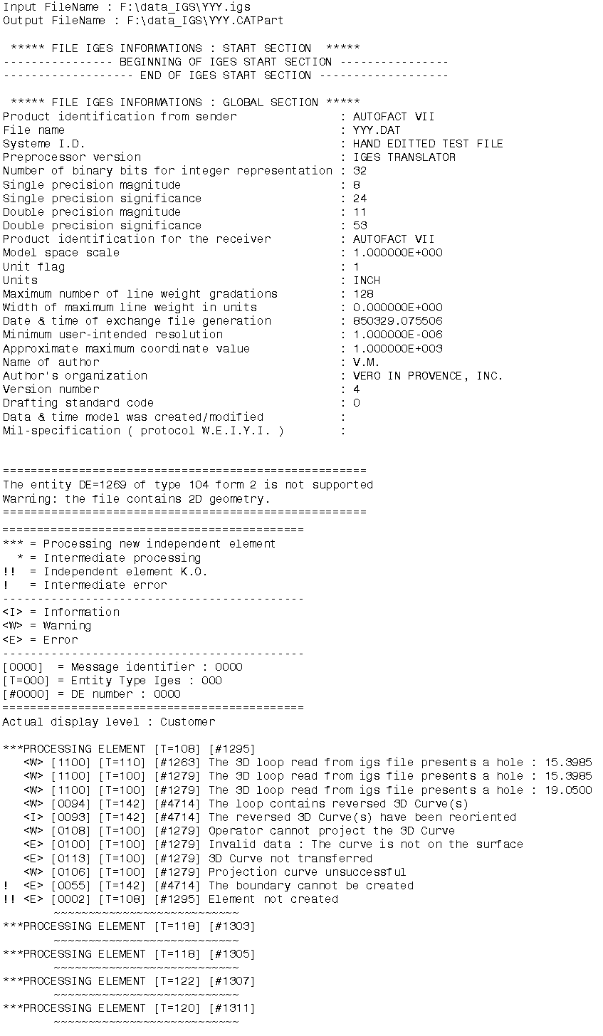
Example of a report file:
|
|
Example of an error file:
 |
| |
Report messages
|
| |
Here are some of the messages that may appear:
- Too many cuts on face boundary.
Tip : Use topological reduction option (in IGES) or curve optimization (in
IGES or STEP) - see User's Guide
These options are accessible via the
Tools/Options/Compatibility/IGES
or
Tools/Options/Compatibility/STEP
dialog boxes, in the Continuity optimization of curves and surfaces
section.
Select the Advanced optimization option and push the
Parameters... button.
For more information, click on the link on IGES above.
|
| |
When the Continuity optimization of curves and
surfaces/Advanced
optimization option
in Tools/Options/Compatibility/IGES is active, the following
warning messages may appear in the report file:
- The BSpine Surface is not C1: Approximation of the surface is
impossible!
This is just a warning, the surface is imported but is not approximated.
- The deformation found of the surface approximation (which is
calculated by isoparameters) is : xx millimeters.
This indicates that the real deformation found is higher than the
Deformation value you have entered in
the Parameters box and that the approximation could not be
performed. When this occurs for several entities,
you will find the following information message at the end of the report
file:
- For a better approximation of BSpline surfaces, you can use a
"Curves and surfaces approximation"
Deformation value of at least : xx millimeters
You can enter this value in the Parameters box of the
Continuity optimization of curves and surfaces/Advanced
optimization option in Tools/Options/Compatibility/IGES.
|
 |
The following points should be remembered:
- The IGES standards 5.2 and 5.3 are supported. The latter is year
2000-compliant.
- Trimmed and bounded surfaces are transformed into faces.
- Solids and volumes are imported as joined shells as well as text,
annotations and 2D geometry are not converted.
- The tolerance used is the default tolerance defined in the Part Design
session.
- Properties such as the original colors, the show status, names (if
they exist) are maintained in your session.
- IGES files must contain only ASCII 1-byte characters.
|
| |
Processing of layers:
- If the IGES file contains a layer 10000, this layer
is tranlated into layer None in V5.
- A layer with a name greater or equal to 1000 is translated into
a layer named with the last three digits, e.g. layer 3250 is translated
into layer 250.
|
|
Processing of names:
- Non ASCII characters are replaced with 1-byte characters, either a
similar one, e.g. a 'e' with an accent is replaced with a plain 'e' (with
no accent), or by an em dash '_'.
- If an IGES entity has a pointer to a "Property Name Entity",
the value of this property will be assigned to the name of the V5 entity.
- If the IGES entity has no pointer to a "Property Name Entity" and
if its "Directory Entry" field #18 is not blank the V5 name will be
computed
by appending field #18 and #19 of the "Directory Entry".
- If the entity has neither a "Property Pointer" nor a non-blank field
#18 an automatic name will be generated.
|
| |
- Product
Identification for Receiver (Global Section, Field #12) will be used
as
the Part Number in the Product Properties and as display and storage names
in V5.
For example, if the file MyFile.igs has a product
identification IGES_Sample,
the storage name will be IGES_Sample.CATPart (not
MyFile.CATPart)
|
|
Processing of Group Associativity:
The Group Associativity, in the IGES Norm, is mapped with the type 402
(ASSOCIATIVITY INSTANCE ENTITY).
There are four form numbers which specify group associativities :
| Form |
Meaning |
| 1 |
Unordered group with back pointers |
| 7 |
Unordered group without back pointers |
| 14 |
Ordered group with back pointers |
| 15 |
Ordered group without back pointers |
For each Group Associativity pointing to a list of entities in the IGES
file, a selection set is created.
This selection set is named with the name of the pointed GROUP entity and
includes all pointed entities. |
 |
- This applies to known Group Associativity forms (Type 402 - forms 1,
7, 14 and 15) only.
- A Selection set pointing to another Selection set cannot be created.
- When a group is pointed by a second group, the entities of the first
group will be pointed by a first
Selection set (mapping the first group) and by a second Selection set
mapping the second group
(including others entities of the second group).
- Only logically dependant IGES entities (Status Number 3-4 = "02" in
D.E. section) can be mapped in a Selection set.
- The
Import Group option activates or de-activates the creation
of Selection Sets.
Processing of 308/408 IGES entities
Processing of trimmed surfaces
IGES Trimmed surfaces are defined by a support surface and one or more
boundaries.
For Trimmed parametric surfaces, the curves of boundaries can have two
representations: one in the model space (3D curves) and another in the
parametric space (2D or P-Curves).
3D Curves can be used on every type of surfaces.
2D curves can be used on B-Spline surfaces (IGES type 128), Ruled surfaces
(IGES type 118 - if the surface is continuous in curvature and not closed) and
Revolution surfaces (IGES types 120/122);
2D curves must be parametric lines (IGES type 110) or P-Nu(r)bs (IGES type
126).
The choice of the curves representation to process depends on the user
preferences and on the IGES file contents. In some IGES files, a
representation can be incorrect.
See
Representation for
Boundaries of Faces in IGES customizing section to learn more about the
management of boundaries representations. |
|
|
| |
IGES Element |
V5 Element |
Notes |
| |
null |
0 |
 |
  |
| |
circular arc |
100 |
circle |
 |
| |
composite curve |
102 |
curve, line, circle |
 |
| |
conic arc - ellipse |
104 form 1 |
curve |
 |
| |
copious data |
106 forms 1-3,15 |
point, curve |
 |
| |
unbounded plane |
108 form 0 |
plane |
From V5R12, even independent planes 108 form 0 are imported.
Independent planes 108 form 0 will be displayed as a small square in V5 |
| |
bounded plane |
108 form 1 |
plane |
 |
| |
line |
110 form 0 |
line |
 |
| |
semi-bounded line |
110 form 1 |
line |
 |
| |
unbounded line |
110 form 2 |
line |
 |
| |
parametric spline curve |
112 |
curve |
 |
| |
parametric spline surface |
114 |
surface |
 |
| |
point |
116 |
point |
 |
| |
ruled surface |
118 |
surface |
 |
| |
surface of revolution |
120 |
surface |
 |
| |
tabulated cylinder |
122 |
surface |
 |
| |
direction entity |
123 |
direction |
|
| |
transformation matrix |
124 |
matrix |
 |
| |
rational B-spline curve |
126 |
curve |
 |
| |
rational B-spline surface |
128 |
surface |
Rational B-spline surfaces are also recognized as planes or
cylinder according to their geometrical properties.. |
| |
offset curve |
130 |
curve, line, circle |
 |
| |
offset surface |
140 |
surface |
 |
| |
boundary (of skin) |
141 |
either included in the translation of a bounded surface, or
curve, line, circle if the transfer of the bounded surface has failed |
If the surface is not of type BSpline and C2 continuous,
only the Geometry type curves "Curve on a parametric surface" and "Boundary"
are taken into account for face creation. 2D Parametric type curves are
ignored. |
| |
curve on parametric surface |
142 |
either included in the translation of a trimmed surface, or
curve, line, circle if the transfer of the trimmed surface has failed |
If the surface is not of type BSpline and C2 continuous,
only the Geometry type curves "Curve on a parametric surface" and "Boundary"
are taken into account for face creation. 2D Parametric type curves are
ignored. |
| |
bounded surface (of skin) |
143 |
surface |
 |
| |
trimmed (parametric) surface |
144 |
surface |
 |
| |
manifold solid B-rep
(consisting of shell
face
loop
edge list
vertex list) |
186 form 0
(514 form 1
510 form 1
508 form 1
504 form 1
502 form 1) |
joined shell |
Creation of a geometrical set or PartBody per shell.
Creation of a PartBody if the shell is closed. |
| |
plane surface entity |
190 form 0-1 |
|
All the surfaces are faces support surfaces :
they must be used with entities of type 143, 144 and 510.
Those surfaces are infinite (not limited).
If a face, supported by one of those surfaces, cannot be correctly
imported, the "invalidFace" created by V5 and containing surfaces and
curves could present visualization problems on infinite surfaces graphic
representation. |
| |
right circular cylindrical surface entity |
192 form 0-1 |
|
| |
right circular conical surface entity |
194 form 0-1 |
|
| |
toroidal surface entity |
198 form 0-1 |
|
| |
subfigure definition (detail) |
308 |
see singular subfigure instance |
 |
| |
color definition |
314 |
color |
 |
| |
associativity instance (group) |
402 forms 1,7,14,15 |
selection set |
See the Group
Associativity |
| |
singular subfigure instance (ditto) |
408 |
simple elements or CATParts |
See the processing of
308/408 IGES entities. |


![]()


