-
Drag-select all of the surfaces in the part.
Click Surface Connection Checker in the Check Geometry toolbar.
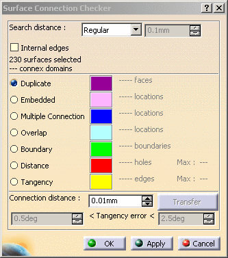
The Surface Connection Checker dialog box appears.
-
A first information appears: the number of surfaces selected.
Enter 0.01mm in the Connection distance box.
Click Apply.
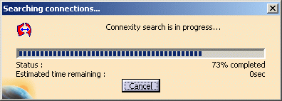
A progress bar indicates the status of the search. If necessary, click Cancel to stop the search.
-
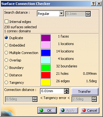
The dialog box is updated with more information on the problems found, with their number, maximum value and the color in which they are highlighted in the viewer.
-
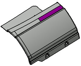
One Duplicate is highlighted in the viewer
(to highlight another problem category, select the corresponding line).
Click Transfer.
-
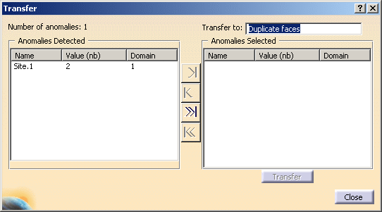
Number of anomalies:1 indicates only one Duplicate site has been found.
This Duplicate site (Site.1) is listed in the Anomalies Detected box.
Optional: right-click Site.1 and select Reframe On to get a better view of the site. -
Transfer to proposes a body named Duplicate faces where you can transfer the duplicate faces.
Click the >>| button.
-
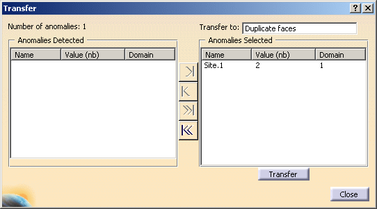
The site is sent to the list of Anomalies Selected.
Click Transfer and then Close. -
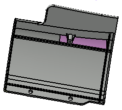
Now select the Embedded line. The Embedded surface is on the lower side of the part.
-
Transfer this surface as explained above. The transfer body proposed is named Embedded cases.

-
Now select the Multiple Connection line. The sites are highlighted in blue.

-
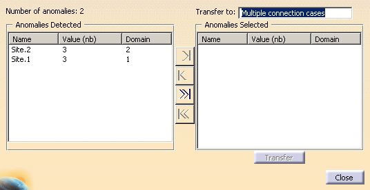
Transfer the Multiple Connection sites as explained above.
The body proposed is named Multiple connection cases.
-
If you select the sites in the dialog box, you can have a clearer view of them:
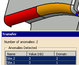
Optional: right-click a site and select Reframe On to get a better view of the site. -
Once all the transfers are done, click OK in the main dialog box.
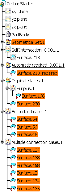
The bodies Duplicate faces.1, Embedded cases.1 and Multiple connection cases.1 have been created in the specification tree.
They contain the defective surfaces. Those bodies are sent in the No Show.
![]()