- with respect to given conditions,
- by analyzing the model to find connexity problems.
You can then:
- order in bodies the sites of the model that should be healed, by importance or location.
- The options selected and the numerical values entered in the dialog box are modal within the session.
- Be careful not to set a Search distance greater than the size of the smallest edges or surfaces present in the document.
- As it aims at finding the greatest possible number of connexity problems, Surface Connection Checker may detect errors that the Surface-Surface Connection command does not detect. However, you may be able to perform a join on the model you have analyzed with Surface Connection Checker. This does not mean that the analysis by Surface Connection Checker is not reliable: Surface Connection Checker is particularly useful if the join is impossible since it provides you with more information than Surface-Surface Connection to find out the connexity problems.
- More Reference Information is available in the Surface Connection Checker Parameters chapter.
-
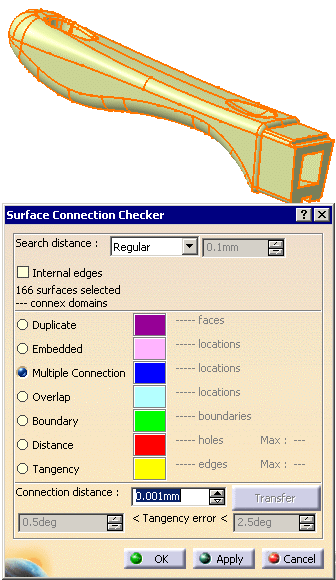
Open file PanHandle.CATPart in the samples directory and drag-select all the surfaces.
-
Click Surface Connection Checker
 in the Check Geometry toolbar.
 -
The Surface Connection Checker dialog box appears.
The number of surfaces selected appears in the upper frame.
-
Let the Search Distance at its default value. Click Apply.
The analysis is performed within the Search distance, i.e. only edges with a distance lower than the Search distance value are taken into account.
The selection information in the upper frame is completed with the number of connex domains found.
The connection problems found are listed in the frame below, with their number and
the maximum value of the gaps found, when relevant.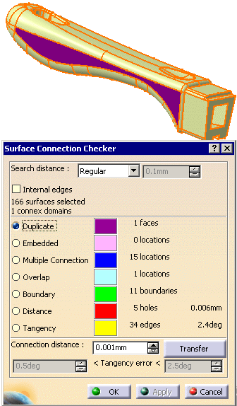
-
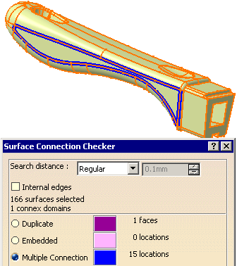
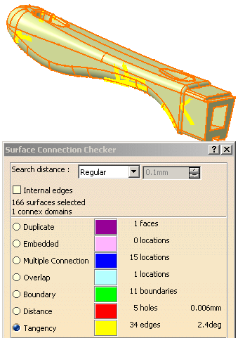
Select each line of this list in turn to highlight the problems in the viewer:
-
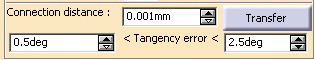
With the Tangency line still selected, you can see that the Tangency error is now available.
Modify the limit values of the tangency error and click Apply.
The information is updated accordingly in the viewer and in the dialog box.
-
Click Transfer. The Transfer dialog box appears, with the list of tangency problems detected,
with the name of the sites and the name of the domain, ordered in decreasing fault value.
Select Site.33. It is highlighted in the viewer.
-
Click the single arrow. The line is transferred to the Anomalies Selected list.
A body G1 gaps is proposed to transfer the defective faces.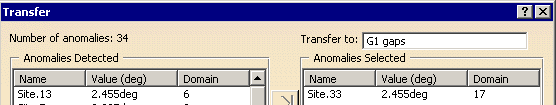
-
Click Transfer. The list of Anomalies Selected is emptied.
The defective faces are transferred to the G1 gaps.1 Geometrical Set for a future healing and hidden in the viewer.
-
Click Close to close the Transfer dialog box. Click OK to validate the process and exit the action
![]()