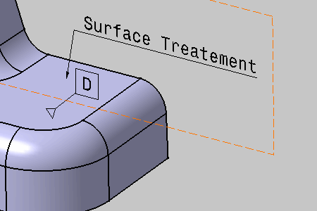
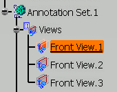
- This scenario illustrates the creation of a datum element by selecting geometry, but you can also select any Part Design or Generative Shape Design feature in the specification tree. In this case, the created annotation will not be attached to the selected feature, but to its geometrical elements at the highest level.
- When you select a non-canonical geometry a datum support, the created
datum will be invalid because there is no enough information to define
datum plane orientation. Two possibilities to avoid this problem:
- Edit the invalid datum and define the plane orientation in the Plane Direction field.
- Create the datum using the Tolerancing Advisor which recognizes automatically the selected geometry as non-canonical and asks you to define the plane orientation in the Plane Direction field. See Creating Datum on Non-Canonical Surfaces.
- See also Datum Principles for more information.
-
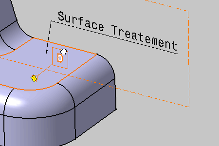
Select the attachment surface of the datum feature.
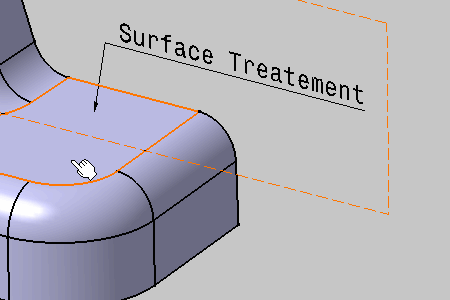
The Datum Feature dialog box displays with D as default identifier. 

The Tools Palette is displayed according to the type of face selected depending on the canonicity. In this scenario the Tools Palette is not used. For more information, refer to Propagating Geometry Selection for Feature Creation.
-
Click OK to create the datum if the identifier corresponds to your choice.
The datum feature is created in a specific annotation plane.
The "Datum" entity (identified as Simple Datum.xxx) is added to the specification tree.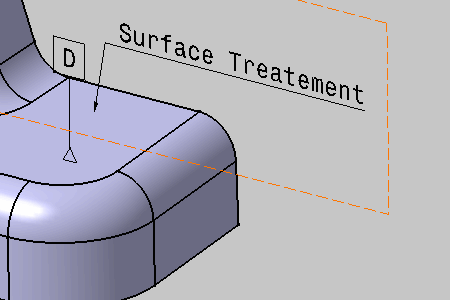
-
Select the datum and drag it anywhere. You can notice that it remains in the annotation plane.
-
Release the datum.
