
The Tools Palette appears whenever you select a command for which specific options or value fields are available. This enables you to know immediately when tools are available for a command.
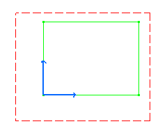
2. Enter the First Point coordinates. For example, H: 0in and V: 0in.
At this step, you can either enter the rectangle second point or width and height values.
4. Enter the Second Point coordinates. For example, H: 3.5in and V: 2.5in.


Note that the grid is not necessarily displayed throughout this documentation. Still, in the Generative Drafting workbench, the grid is set by default. If you need to hide or display the grid, go to Tools > Options> Mechanical Design> Drafting> General tab and check the Display option.
![]()